|
| Overview | All Modules | Tutorial | User's Guide | Programming Guide |
| Previous | COVISE Online Documentation | Next |
Supported tracking devices are the Polhemus FASTRAK (POLHEMUS), the Ascension Motionstar (MOTIONSTAR), and the Ascension Flock of Birds (FOB). Additionally all devices supported by the CAVELIB can be used if a trackerdeamon from CAVELIB is installed. These tracking systems use electromagnetic fields to determine the position and orientation of a remote object. The Polhemus FASTRAK and the Ascension Flock of Birds are connected to the serial port of the computer, the Ethernet Motionstar system is a PC where each sensor is connected to an internal Motionstar receiver (ISA) card. The PC transmitts the position and orientation data via ethernet to the graphics workstation.
The input devices mouse (SPACEPOINTER), the Spaceball (SPACEBALL), the Phantom (PHANTOM), the Flybox (COVER_FLYBOX) and the Beebox (COVER_BEEBOX) and can be used only for hand tracking.
The Ascension and Polhemus trackers can also be combined with other commercial or selfmade button devices. Supported button devices are the ICIDO Mike (MIKE), the division Joystick (DVISION), the CEREAL Box (CEREAL), the Virtual Presense xxx (VIRTUAL_PRESENCE), the Pinch Glove (PINCH) and all devices supported by cavelib.
COVERConfig
{
    ....
    TRACKING_SYSTEM  <POLHEMUS|MOTIONSTAR|FOB|CAVELIB|
                      SPACEBALL|SPACEPOINTER|COVER_BEEBOX|COVER_FLYBOX|PHANTOM>
    ....
}
All supported tracking systems need a common configuration section TrackerConfig in which the receiver addresses and the offsets between the tracker coordinate system and the COVER coordinate systems are described and special configuration section where for example the serial port or the IP address is described. The special configuration sections have the same name as the devive, for example PolhemusConfig.
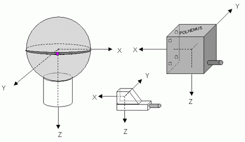
Depending how the transmitter and sensors are mounted, the coordinate systems of the electromagnetic trackers have to be transformed to match the coordinate systems of COVER. COVER coordinate systems are Performer coordinate systems, this means xaxis right, yaxis into the screen, and zaxis up.
The COVER world coordinate systems is specified implicit when you specify the position and orientation of the screens (see Graphics Board and Display ). The origin of a Powerwall is typically the center of the screen, the origin of a CAVE is typically the center of the cube.
The COVER viewer coordinate system has its origin between the users eyes. The COVER hand coordinate system has its origin in the center of the hand device.
The transmitter position and orientation have to be choosen individually for each virtual environment. It should be far away from metal, monitors and current cables. The sensor for headtracking is normally mounted at one of the frames of the eyeglasses. The sensor for the hand device is normally integrated into the device.
The position and orientation offsets, the number of receivers and the receiver addresses (or station numbers) are stored in the section TrackerConfig.
The orientation is defined in euler angles (H = heading = rotation around z, P = pich = rotation around xaxis, R = roll = rotation around y axis). The matrix is created in the order R*P*H. You first rotate around roll, then pitch and then heading. The order in the covise.config file is HPR! While the translation offset can be measured or estimated, the euler angles have to be found by mentally rotating a transmitter, which has the same orientation as the world coordinate system, to the orientation of the real transmitter. First imagine a rotation around the (world) yaxis, then around the (world) xaxis and at least around the (world) zaxis.
TrackerConfig
{
    TRANSMITTER_OFFSET  <x in cm> <y in cm> <z in cm>
    TRANSMITTER_OFFSET  <heading in degree> <pitch in deg> <roll in deg>

    HEADSENSOR_OFFSET  <x in cm> <y in cm> <z in cm>
    HEADSENSOR_ORIENTATION  <heading in degree> <pitch in deg> <roll in deg>

    HANDSENSOR_OFFSET  <x in cm> <y in cm> <z in cm>
    HANDSENSOR_OFFSET  <heading in degree> <pitch in deg> <roll in deg>

    NUM_SENSORS <n>
    HAND_ADDR <station nr or address>
    HEAD_ADDR <station nr or address>
}
At the end of this chapter you find two examples, a CAVE with a Motionstar and a workbench with a Polhemus system.
If you combine the Ascension or Polhemus tracker with an external button device you have to indicate this in the section COVERConfig with the keyword BUTTON_SYSTEM.
COVERConfig
{
    ....
    BUTTON_SYSTEM  <MIKE|VIRTUAL_PRESENCE|PINCH|CEREAL|CAVELIB|DIVISION>
    ....
}
As these button devices use different serial ports than the tracking systems, you have to describe it in the section ButtonConfig.
ButtonConfig
{
    SERIAL_PORT <portname>
    ...
}
Most button devices have more than one buttons. As you need only one button to select functions from the 3D menu, you can put the most often used function XFORM and DRIVE on the other buttons. For example if you put the function XFORM on button number three, you don't have to select this from the menu first but can directly move the world while the third button is pressed.
The mapping of button numbers to functions is also described in the section ButtonConfig:
ButtonConfig
{
    MAP 1   <function>
    MAP 2   <function>
    ...
}
function can be ACTION_BUTTON, DRIVE_BUTTON or XFORM_BUTTON. With ACTION_BUTTON the button which is used for functions selected from the menu is meant.
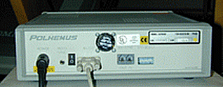
There are two types of transmitters: the standard transmitter which is a 10 cm box, and the long ranger, which is a transparent sphere of 30 cm diameter.
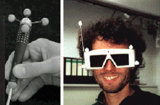
COVER supports one sensor for headtracking and the polhemus stylus as 3d input device.
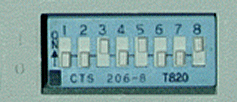
Choose a baud rate with the IO-Select switches on the rear side of the SEU. The meaning of the IO-Select switches is:
| Position | Function |
|---|---|
| 1 | Baud Rate Select |
| 2 | Baud Rate Select |
| 3 | Baud Rate Select |
| 4 | Hardware Handshake Select |
| 5 | Character Width |
| 6 | Parity Select |
| 7 | Parity Select |
| 8 | IO Select UP for RS232 |
For COVER you can select only the baud rate with the first three switches. The other functions can't be configured. Their value must be: Switch_4 = 0, Switch_5 = 1, Switch_6=0, Switch_7=0, Switch_8=1. The meaning of the baud rate switches is:
| Baud Rate | 1 | 2 | 3 |
|---|---|---|---|
| 1200 | 0 | 0 | 0 |
| 2400 | 1 | 0 | 0 |
| 4800 | 0 | 1 | 0 |
| 9600 | 1 | 1 | 0 |
| 19200 | 0 | 0 | 1 |
| 38400 | 1 | 0 | 1 |
| 57600 | 0 | 1 | 1 |
| 115200 | 1 | 1 | 1 |
On SGI Onyx systems we recommend 19200 or 38400. The selection for 19200 is: 00101001 (0=down, 1=up).
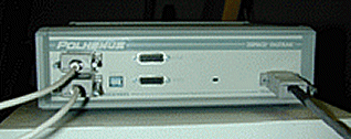
Connect the transmitter and the receivers to the SEU (frontside).
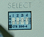
Select the stations with the station select switches.
Attention: On some Polhemus FASTRAK SEUs the label next to the switches says on=up. This is wrong. According to the manual and our experience on=down.
Switch the SEU on and wait until the green led stops blinking.
Test the Polhemus system with the progamme polhemustest, which you find under covise/sgin32/bin. It should continously print the position of the two sensors.
polhemustest /dev/ttyd2 19200 1 2
COVERConfig
{
    ...
    TRACKING_SYSTEM POLHEMUS
    ....
}

TrackerConfig
{
    NUM_SENSORS                 <n>
    HAND_ADDR                   <station no>
    HEAD_ADDR                   <station no>
    TRANSMITTER_OFFSET          <x y z>
    TRANSMITTER_OFFSET          <h p r>
    HEADSENSOR_OFFSET           <x y z>
    HEADSENSOR_ORIENTATION      <h p r>
    HANDSENSOR_OFFSET           -90 0 90
    HANDSENSOR_ORIENTATION      <h p r>
}

PolhemusConfig
{
    SERIAL_PORT                 </dev/ttyd...>
    BAUDRATE                   <baudrate>
    HEMISPHERE                  <x y z>
}
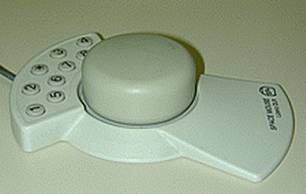
The receivers can also be a 6DOF mouse which is a receiver with additionally 3 buttons.
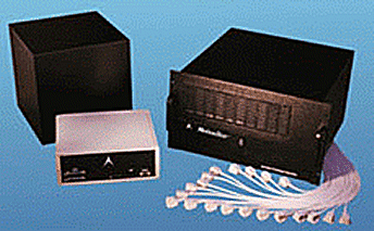
The ERT is connected to the ERC box. The ERC box is connected to the PC through a serial cable. The receivers are connected to the receiver controller card. The PC is connected to the graphics workstation using a twisted pair cable.The ethernet cable should not be connected to the LAN, because hight traffic on the LAN could delay the tracking. Please refer to the Ethernet Motionstar Documentation for configuring a system which was not setup to operate in ERC mode.
The PC runs under DOS. After booting DOS a programm (NAME?) which reads the receiver controller cards, computes position and orientation values and qrites them to the Ethernet Interace is started. Please note that under DOS you need a license for the TCP programme called (NAME?).
COVERConfig
{
    TRACKING_SYSTEM MOTIONSTAR
}
TrackerConfig
{
    NUM_SENSORS                 <n>
    HAND_ADDR                   <address>
    HEAD_ADDR                   <address>
    TRANSMITTER_OFFSET          <x y z>
    TRANSMITTER_ORIENTATION     <h p r>
    HEADSENSOR_OFFSET           <x y z>
    HEADSENSOR_ORIENTATION      <h p r>
    HANDSENSOR_OFFSET           0 0 0
    HANDSENSOR_ORIENTATION      90 0 0
}
The motionstar system has a single Ethernet IP address. The default IP address is 192.200.9.50, but you can
change it to a custom IP address.
Insert the IP address into the file covise.config in the section MotionstarConfig
MotionstarConfig
{
    IP_ADDRESS                  <address>
    HEMISPHERE                  <FRONT|REAR|LEFT|RIGHT|UPPER|LOWER>
    DualTransmitter             <ON|OFF>
    # only for wireless systems instead configuring a button system
    MotionstarButtonSystem      <MIKE VIRTUAL_PRESENCE CEREAL CAVELIB DIVISION>
    SamplingRate                <default is 80>
    BIOS                        <OLD|NEW>
}
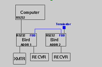
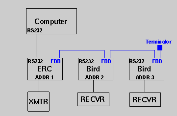
The birds are connected to each other with the Fast Bird Bus (FBB) and to the computer through the serial port. For COVER you need two birds. The transmitter is connected to the first bird, which is also connected to the computer.
When an ERT is used, you need additionally the ERC box. The ERC is connected to the computer and the ERT is connected to the ERC. The ERC and the other Birds are connected through the FBB.
Each Bird and the ERC can be configured for RS232, or RS485 use with internal jumpers. Normally Ascension has pre-set the jumpers for your interface. In case you have to change it, refer to page 6 in the FOB Installation and Operation Guide. The FOB has to be connected through the RS232 interface for COVER.
The Birds and ERC can be operated in two addressing modes:
normal addressing mode and expanded addressing mode. The Flock of Birds
needs to be operated in normal addressing mode for COVER. This mode is set
with the dip switches 4567 and 8 set to TEST (ON=DOWN).
For changing the address mode set the switches
of each bird to [4=on 5=on 6=on 7=off 8=on] (see page 54 in the FOB Installation
and Operation Guide) and turn the power on. When the front panel indicator blinks,
the normal addressing mode has been set.
| |||||||||||||||||||||||||||
With the dip switches 4567 and 8 set to FLY (off), the address is configured: The first bird gets address 1, the second birds gets address 2. In case the ERC is the first bird, it gets address 1, the first bird gets address 2 and the the second bird gets address 3.
The baud rate is set with the switches 1,2 and 3, the following example is for baud rate 19200.
| |||||||||||||||||||||||||||||||||||||||||||||
COVERConfig
{
   ....
    TRACKING_SYSTEM         FOB
    ...
}

TrackerConfig
{
    NUM_SENSORS             <n>
    HAND_ADDR               <address>
    HEAD_ADDR               <address>
    TRANSMITTER_OFFSET      <x y z>
    TRANSMITTER_OFFSET      <h p r>
    HEADSENSOR_OFFSET       <x y z>
    HEADSENSOR_ORIENTATION  <h p r>
    HANDSENSOR_OFFSET       0 0 0
    HANDSENSOR_ORIENTATION  90 0 0
}

FobConfig
{
    SERIAL_PORT             </dev/ttyd...>
    BAUDRATE                <baudrate>
    HEMISPHERE              <FRONT|REAR|LEFT|RIGHT|UPPER|LOWER>
    FULLRANGE               <ON|OFF>
}
The transmitter type and hemisphere are configured in the section FLockConfig. The hemisphere can be FRONT, REAR, UPPER, LEFT or RIGHT.
See Pg. 64 in the FOB Installation and Operation Guide for a sketch of the FOB coordinate system.
FOBserver [options]  dev0[=map0] dev1[=map1] ...

   devX = Device Numbers of Receivers (1..14)
   mapX = COVER device numbers (0..31)

Options:

   -t <host:port>          set target to send tracking UDP packets
   --target=host:port      (default: localhost:7777)

   -r <value>              transmission speed in Packets/sec
   --rate=value            (default: 20)

   -d <serialPort>         Device name of serial port
   --device=serialPort     (default: SGI /dev/ttyd1, Linux /dev/ttyS2)

   -b <baudrate>           Speed of serial interface
   --baudrate=<baudrate>   (default 19200 Baud)

   -H <hemisphere>         Hemisphere selection: FRONT REAR LEFT RIGHT UPPER LOWER
   --Hemisphere=Hemisphere (default: FRONT)

   -m <selection>          Flock mode selection: STREAM or POINT
   --mode=<selection>      (default: STREAM)

   -n <numBirds>           Number of Flocks attached: ERC counts as 1 bird!
   --numbirds=number       (default: number of given stations)

   -h, --help              Show this help
Examples:
FOBserver -d /dev/ttyS2 1 2
Start a Server to localhost:7777, reading with 19200 Baud on /dev/ttyS2 from a Flock with 2 stations. Use FRONT Hemisphere and STREAM mode, transmit stations 1 and 2 to COVER.
   FOBserver -d /dev/ttyS2 1=0 2=4

   Same as before, but send station 1 results with ID=0 and station 2 with ID=4

   FOBserver --target=devil:7234 --device=/dev/ttyS2 --baudrate=38400 \
             --hemisphere=LOWER --mode=POINT --numbirds=4  4=0 3=1
Start a Server to host "devil" Port 7234, reading from a Flock with Extended Range Transmitter and 3 receivers using LOWER hemisphere and POINT mode. Send Station 4 results with ID=0 and station 3 results with ID=1
Startup:
 # /common/FOBserver -d /dev/ttyS2 1 2

  +-----------------------------------------------------+
  + VRC FOBserver 2.0           (C) 2003 VirCinity GmbH +
  +-----------------------------------------------------+
  + Settings:                                           +
  +   UDP Target:        localhost:7777                 +
  +   Send Rate:         20.0 Packets/s                 +
  +   Serial Interface:  /dev/ttyS2                     +
  +   Baudrate:          19200                          +
  +   FOB Hemisphere:    FRONT                          +
  +       Mode:          STREAM                         +
  +       Birds:         2  (including ERT if exist.)   +
  +-----------------------------------------------------+
  + Mapping:                                            +
  +   Bird 1   --> COVER: ID 1                          +
  +   Bird 2   --> COVER: ID 2                          +
  +-----------------------------------------------------+
  BirdNo  Access. Rec.    Trans.  ERT
   1       X       X       X       -
   2       X       X       -       -
   3       -       -       -       -
   4       -       -       -       -
   5       -       -       -       -
   6       -       -       -       -
   7       -       -       -       -
   8       -       -       -       -
   9       -       -       -       -
  10       -       -       -       -
  11       -       -       -       -
  12       -       -       -       -
  13       -       -       -       -
  14       -       -       -       -

VRC 1   0 [   15   -73    22] - [-0.18  0.50  0.85  0.98  0.18  0.10 -0.11  0.85 -0.52]
                                                                       - [ 0.00  0.00 ]
VRC 2   0 [   33   109    87] - [ 0.44 -0.64 -0.63 -0.59 -0.74  0.34 -0.68  0.22 -0.70]
                                                                       - [ 0.00  0.00 ]
---
VRC 1   0 [   15   -73    22] - [-0.18  0.50  0.85  0.98  0.18  0.10 -0.10  0.85 -0.52]
                                                                       - [ 0.00  0.00 ]
VRC 2   0 [   32   108    87] - [ 0.45 -0.64 -0.63 -0.59 -0.74  0.33 -0.67  0.22 -0.70]
                                                                       - [ 0.00  0.00 ]
---
VRC 1   0 [   15   -73    22] - [-0.18  0.50  0.85  0.98  0.18  0.10 -0.11  0.85 -0.52]
                                                                       - [ 0.00  0.00 ]
VRC 2   0 [   32   109    87] - [ 0.46 -0.64 -0.62 -0.58 -0.74  0.34 -0.68  0.20 -0.71]
                                                                       - [ 0.00  0.00 ]
---
...
COVER can use trackd as input instead of it's own device drivers. TRACKING_SYSTEM and BUTTON_SYSTEM have to be set to CAVELIB. In the section CaveLibConfig you specify the shared memory id. The values in the following example are the default values of trackd.
The trackd world coordinate system is OpenGL-like
In the following example the trackd origin is on the bottom of the CAVE. The tracking system is an intersense 900 and trackd is used instead of COVER's own driver.
COVERConfig
{
    ....
    TRACKING_SYSTEM CAVELIB
    BUTTON_SYSTEM CAVELIB
    ....
}

CaveLibConfig
{
   TRACKER_SHMID  4126
   WAND_SHMID     4127
}

TrackerConfig
{
    HAND_ADDR                   1
    HEAD_ADDR                   0

    # cover origin is in the middle of the cave
    TRANSMITTER_OFFSET            0   0   -150
    # rotation around pitch (x)
    TRANSMITTER_ORIENTATION       0  90      0

    HEADSENSOR_OFFSET             0    0    0
    HEADSENSOR_ORIENTATION        0    0    0

    HANDSENSOR_OFFSET             0    0    0
Features not supported by COVER:
For further information about A.R.T tracking see http://www.ar-tracking.de .
Warning: Some devices with buttons, e.g. Mike devices, are Bodies, not FlySticks, because they transfer their button information by an own serial connected interface. This can be identified on the controller PC: FlySticks show "F<number>" in their ID field.
COVERConfig
{
    TRACKING_SYSTEM DTRACK
}

TrackerConfig
{
    NUM_SENSORS                 <n>
    HAND_ADDR                   <flystick_id+10> or <body_id>
    HEAD_ADDR                   <body_id>
    TRANSMITTER_OFFSET          <x y z>
    TRANSMITTER_ORIENTATION     <h p r>
    HEADSENSOR_OFFSET           <x y z>
    HEADSENSOR_ORIENTATION      <h p r>
    HANDSENSOR_OFFSET           0 0 0
    HANDSENSOR_ORIENTATION      <h p r>
}

DTrackConfig
{
    Port                          <port number default: 5000>
}
Important:
The control window of the A.R.T tracking counts the Bodies and FlySticks 1,2,... and F1,F2,... while messages sent to the application start counting from 0. The IDs used in covise.config are those received by COVER, so when using the Body "1" for head-tracking and FlyStick "F1" displayed in the control window, you must specify
    HEAD_ADDR                   0
    HAND_ADDR                   10
in the covise.config file.
The ARTserver receives A.R.T tracking information, transforms it to VRC protocol, removes recundancies if necessary, and transfers it to COVER.
If you start it w/o arguments, you get the user information:
ARTserver [options]  dev0=map0 dev1=map1 ...

   devX = Device Numbers of Bodies    (B1, B2, ...)
                         or FlySticks (F1, F2, ...)
   mapX = COVER device numbers (0..31)

Options:

   -t <host:port>           set target to send tracking UDP packets
   --target=host:port       (default: localhost:7777)

   -r <value>               transmission speed in Packets/sec
   --rate=value             (default: 20)

   -p <portNo>              Port number to receive A.R.T Tracker
   --port=portNo            (default 5000)
   -s <host:portNo>         Send A.R.T Tracker Start/Stop command to
   --sendStart=host:portNo  (default none, do not use "receive port"
Examples:
   ARTserver F1 B1          Receive ART information on port 5000, and send
                            it with 20 Hz frequency to localhost Port 7777.
                            send Flystick F1  -->  COVER ID 0
                            send Body 1       -->  COVER ID 1

   ARTserver F1=2 B1=3      as before, but
                            send Flystick F1  -->  COVER ID 1
                            send Body 1       -->  COVER ID 3

   ARTserver --sendStart=10.0.0.1:5001 F1=2 B1=3
                            as before, but send signal Tracker PC at address
                            10.0.0.1, Port 5001 to start/stop measurement
                            before/after ARTserver execution
At start time you at an information window, afterwards you get once per second the current values of the parameters:
ARTserver F1 B1

  +-----------------------------------------------------+
  + VRC ARTserver 1.2           (C) 2003 VirCinity GmbH +
  +-----------------------------------------------------+
  + Settings:                                           +
  +   ART port:          5000                           +
  +   ART startup:       (Not used)                     +
  +   UDP Target:        localhost:7777                 +
  +   Send Rate:         20.0 Packets/s                 +
  +-----------------------------------------------------+
  + Mapping:                                            +
  +   Target F1   --> COVER ID 0                        +
  +   Target B1   --> COVER ID 1                        +
  +-----------------------------------------------------+

INFO: DTrack server started
INFO: DTrack server forked
VRC 0   0 [   15   -73    22] - [-0.18  0.50  0.85  0.98  0.18  0.10 -0.11  0.85 -0.52]
                                                                       - [ 0.00  0.00 ]
VRC 1   0 [   33   109    87] - [ 0.44 -0.64 -0.63 -0.59 -0.74  0.34 -0.68  0.22 -0.70]
                                                                       - [ 0.00  0.00 ]
---
VRC 0   0 [   15   -73    22] - [-0.18  0.50  0.85  0.98  0.18  0.10 -0.10  0.85 -0.52]
                                                                       - [ 0.00  0.00 ]
VRC 1   0 [   32   108    87] - [ 0.45 -0.64 -0.63 -0.59 -0.74  0.33 -0.67  0.22 -0.70]
                                                                       - [ 0.00  0.00 ]
---
VRC 0   0 [   15   -73    22] - [-0.18  0.50  0.85  0.98  0.18  0.10 -0.11  0.85 -0.52]
                                                                       - [ 0.00  0.00 ]
VRC 1   0 [   32   109    87] - [ 0.46 -0.64 -0.62 -0.58 -0.74  0.34 -0.68  0.20 -0.71]
                                                                       - [ 0.00  0.00 ]
---

   ID  Buttons x     y     z     Rotation                                        Analog

Buttons:  Bits 0-7 for max. 8 buttons, Bit=1 pressed, Bit=0 released
For testing the magellan device you can run the confidence test '/usr/sbin/confidence'.
For the COVER and the inventor renderer module you have to use the old name "spaceball". You must create the file /usr/lib/X11/input/config/magellan with the following contents:
x_init{

name "spaceball"

}
After that you should make a reboot.
Note: Please make sure that the serial interface
/dev/ttyd<no>or
/hw/ttys/ttyd<no>is readable and writable for the user, where
<no>specifies the number of the serial interface the spaceball is connected to.
COVERConfig
{
    ....
    FREEZE              ON
    VIEWER_POSITION     0.0 -500.0 0.0
    ....
}
As mentioned above the space mouse can be used only as hand input device. Without any interaction selected from the menu the space mouse steers the laser sword. To select an menu item, move the laser sworld so that it points to the menu item and then click on button 1. For interactions like XFORM (“move world”), where you have to keep the button pressed, you have to keep the button 1 pressed to perform the movement of the scene.
Instead of pressing the button 1 and keep it pressed you can also click on button 5 (without keeping it pressed). To release it, click on button 5 again. In addition you can use the following features:
SPACEBALL has to be added as tracking system in COVERConfig; depending on the scene size and the frame rate you may want to change the translation and rotation rate of the space mouse:
COVERConfig
{
    ....
    TRACKING_SYSTEM     SPACEBALL
    ....
}
SpaceballConfig
{
    SCALE_TRANSLATION   <tfactor>
    SCALE_ROTATION      <rfactor>
}
Recommended values are 1.0 for translation and 5.0 for rotation; if you want more precision for rotation, select a value less than 5.0.
The MIKE device supplies button information only, no tracking information. So the MIKE server has to send its values to an ID different from the tracking device used, and BUTTON_ADDR in TrackerConfig has to point to the corresponding ID. If e.g. in the example above A.R.T. tracking uses the IDs 0 and 1, the MIKE server may send its values to ID 2.
MIKEserver [options]  coverID

   coverID = Station ID for COVER's BUTTON_ADDR config

Options:

   -t <host:port>          set target to send tracking UDP packets
   --target=host:port      (default: localhost:7777)

   -d <serialPort>         Device name of serial port
   --device=serialPort     (default: SGI /dev/ttyd1, Linux /dev/ttyS2)
Examples:
   MIKEserver 3            Read MIKE device at default port and send
                           data to localhost:7777 with ID=3

   MIKEserver -d /dev/ttyS15 -t vircinity:6666 4
                           Read MIKE device at /dev/ttyS15 and send data
                           to Host "vircinity" Port 6666 with ID=4
COVER has a new Tracking-Device, called 'VRC'.
Add in Covise-Config:
COVERConfig
{
    ...

    TRACKING_SYSTEM             VRC
}
The VRC system is not a standalone tracker, but a receiver for externally generated tracking and button information. This information can be supplied by UDP via the network and is generated by device servers that have to be started separately.
VRC tracking is configured in a dedicated section:
VRCTracker
{
  Port         <Port number>
  DebugLevel   <0..4>
  Unit         <measurement unit>
}
The VRC tracker is capable to receive input from more than one device simultaneously. The channels are identified by IDs [0..31]. Use section TrackerConfig to specify which channel contains which information.
TrackerConfig
{
    ...
    HEAD_ADDR   <ID>
    HAND_ADDR   <ID>
    BUTTON_ADDR <ID>
    ANALOG_ADDR <ID>
    ...
}
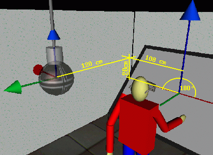
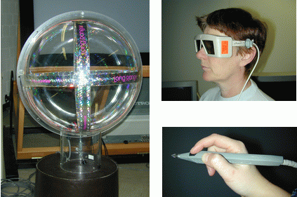
In the RUS workbench example the trackings system is a polhemus FASTRAK. The SEU is connected to the second serial port of the Onyx, the baud rate is 19200. A long ranger transmitter is connected to the SEU. The longranger is mounted at the ceiling, therefore we select the hemisphere with the cenit in -z direction (the hemisphere direction is defined in the transmitter coordinate system).
The stylus,connected to station 1, is used as input device and a sensor, connected to station 2 is used for headtracking. The sensor is mounted at the left side of the glasses.
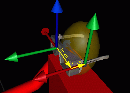
The transmitter position offset TRANSMITTER_OFFSET_POS can be easily measured. Please note that contrary to the screen dimensions the offset is defined in centimeters. The image above shows the world coordinate system with the origin at the center of the workbench and the transmitter coordinate system with the origin in the longranger sphere.
The orientation of the transmitter coordinate system is also different from the world coordinate system. As mentioned above we have to determine the euler angles. We have to rotate an imaginary transmitter with the same orientation as the world coordinate first around the (world) y-axis, then around the (world) x-axis and at least around the (world) z-axis. It is easy to see that it needs only a rotation of 180 degree around the z axis to match the imaginary transmitter with the real one.
The position of the viewer coordinate system in the sensor system (the sensor is mounted at the left frame of the glasses), can be measured (see image). To find the euler angles, we rotate an imaginary sensor with the same orientation as the viewer coordinate system, -90 degree around the y-axis, and -90 degree around the z-axis to match the real sensor system.
As the sensor in the stylus is always mounted in the same way, it doesn't need to be described here.
PolhemusConfig
{
    SERIAL_PORT             /dev/ttyd2 19200
    HEMISPHERE              -1 0 0
    HAND                    POLHEMUS_STYLUS     1
    HEAD                    POLHEMUS_SENSOR     2
    TRANSMITTER_OFFSET_POS  -108 -120 20
    TRANSMITTER_OFFSET_EULER 180 0 0
    SENSOR_OFFSET_POS        5 0 10
    SENSOR_OFFSET_EULER     -90 0 -90
    STYLUS_OFFSET_POS        0 0 0
    STYLUS_OFFSET_EULER      90 0 0
}
| Previous | Next |
| Authors: Martin Aumüller, Ruth Lang, Daniela Rainer, Jürgen Schulze-Döbold, Andreas Werner, Peter Wolf, Uwe Wössner |
| Copyright © 1993-2022 HLRS, 2004-2014 RRZK, 2005-2014 Visenso |
COVISE Version 2021.12
|