|
| Overview | All Modules | Tutorial | User's Guide | Programming Guide |
COVISE Online Documentation | Next |
VR Environments today come in various flavours First you have to differentiate between head mounted displays (HMDs) and projection based virtual environments. Both types are supported by OpenCOVER. For stereo you need either a graphics board which supports active stereo video formats, such as NVIDIA Quadro boards, a graphics board with two video outputs, a computer with two graphics boards or two computers connected to each other via a LAN. Some display devices such as Autostereoscopic displays can be driven by a single graphics output by using interlaced stereo modes. Some of those are also supported by OpenCOVER. For driving more than one display device like in tiled displays or multiple screen projection environments, either a cluster of computers, multiple graphics boards in one computer or any combination of those are nedded. The following sections explains which combinations are supported by OpenCOVER and how they are configured.
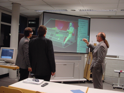
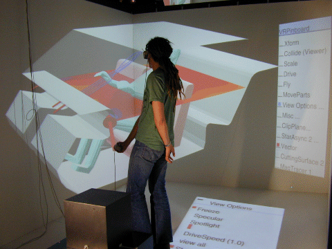
OpenCOVER supports all types of Virtual Environments (VEs) with spatially fixed planar screens like a CAVE, Powerwall, Workbench or Holobench. The VEs differ in the number of screens, the number of people they are suited for and the level of immersion.
A Powerwall is a semi-immersive system with one big flat translucent canvas. The image is projected from behind, so that people don't stand in the optical path of the projector. The resolution can be enhanced by composing the final image from several graphics boards, video outputs or several computers. A Powerwall is well suited for presentations for large groups. As the user is not completely surrounded by screens the immersion is lost when he looks too far to the left or right, up or down.
A Workbench is a semi-immersive system with a single translucent canvas. The workbench dimensions are similar to a drawing board and often the screen can be tilted back. The advantage of a workbench is, that the user can reach every point on the screen. It is suitable for small groups (3-4 persons). The stereo impression and therefore the immersion gets lost when objects in the scene are cut by the frame of the workbench.
The Visenso Cykloop is a mobile one-screen backprojection system with a screen size of 160 x 120 cm.
A CAVE (TM) is a system where the walls form a cube. The first CAVE was built at EVL. There are CAVEs with 4 screens (left, front, right and bottom), with 5 screens, (additionally the ceiling) and 6 screens. The more screens the CAVE has the better is the immersion. The dimension of one cube side is typically 3000 mm x 3000 mm. A CUBE is suited for smaller number of persons up to six or eight.
A Holobench has two screens, a front and a bottom screen. The bottom screen is on the height of a table and the dimensions are like the ones of a workbench. A Holospace also has a front and a bottom screen, but the bottom screen is on the floor and the dimensions are like a CAVE.
Tiled displays are monoscopic or autostereoscopic highres displays composed out of an array of flat pannel displays.
To improve the immersion in the VE, COVER supports stereo. Stereo means that two images are presented to the user, one computed from the view of the left eye, and one computetd from the view of the right eye. Stereo can be turned on or off by setting the Stereo value to "ON" or "OFF". The default is "OFF"!
<Stereo vaue="ON" />
The separation between the two eyes can be specified with separaton attribute in the Stereo entry. The actual distance between the eyes differs from human to human but the default of 60 mm is good in most cases. If you want to disable stereo for taking pictures or a movie, you can temorarily disable the stereo separation in the 3D GUI under View options or set this value to 0.
<Stereo separation="60" />
Special glasses ensure that each eye sees only the appropriate image. As in natural viewing, the brain forms a 3D image from the two images from two different perspectives.
There are several methods for stereo viewing: red-green stereo, interlaced stereo and most important: active and passive stereo.
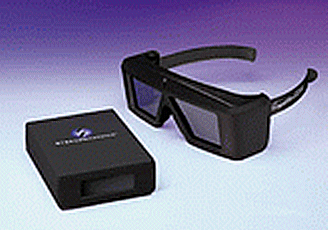
In active stereo, the graphics card of the computer needs to be able to switch to a video mode, where the left and the right image are stored in different areas of the video memory. Every video frame it switches between the left and the right image. This mode is called QuadBuffer mode. Special glasses called shutter glasses which can make the glass opaque are synchronised with the graphics card trough an infrared emitter. When the graphics card displays the left image, the right glass is set to opaque and vice versa.
This stereo mode is supported among others on NVIDIA Quadro boards and AMD/ATI FireGL boards as well as most SGI Systems. In order to enable QuadBuffer Stereo, you have to modify the X-Configuration according to your driver's documentation. On WindowsXP and Vista, you have to open your graphicsdriver controll pannel, go to 3D options and enable stereo. On Linux systems, you have to modify your X configuration, typically located in /etc/X11/xorg.conf for ATI boards you have to add the following to your xorg.conv:
Option "Stereo" "on"
for NVIDIA boards you have to select an appropriate Stereo mode similar to the following line, see /usr/share/doc/NVIDIA_GLX-1.0/README.txt
Option "Stereo" "3"After restaring our X server, you can verify that your graphics board is in stereo mode by running "glxinfo". In the output, there is a column called "st ro" (for stereo). Some of the lines have to contain a "y" in that column
   visual  x  bf lv rg d st colorbuffer ax dp st accumbuffer  ms  cav
 id dep cl sp sz l  ci b ro  r  g  b  a bf th cl  r  g  b  a ns b eat
----------------------------------------------------------------------
0x21 24 tc  0 32  0 r  y  .  8  8  8  0  4 24  8 16 16 16 16  0 0 None
0x22 24 tc  0 32  0 r  y  y  8  8  8  0  4 24  8 16 16 16 16  0 0 None
0x23 24 tc  0 32  0 r  y  .  8  8  8  8  4 24  8 16 16 16 16  0 0 None
On SGI Maximum Impact and Infinite Reality Systems it is possible to switch between a mono and a stereo video format on the fly as longs as the "managed area" remains the same.
If you want to switch the monitor into stereo only when COVER is running you can specify the setmon command with the command attributes to the Stereo and Mono entry.
Example:
<Stereo command="/usr/gfx/setmon -n 1024x768_96s" />
<Mono command="/usr/gfx/setmon -n 1280x1024_76" />
With setmon only standard video formats can be loaded. Infinite Reality Systems support also custom video formats which can be loaded with the command ircombine. If the video mode should not be changed (for example because the correct mode is already running all the time), set command to and empty string. (this is the default)
Finally, you have to select a stereo visual for rendering. you can do that with the stereo attribute in the appropriate Window Entry.
<Window index="0" width="1280"height="1024" decoration="false" stereo="true" />
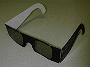
In passive stereo the left and the right image are presented at the same time, but at two different video outputs which are connected to two projectors. Each projector has a polarised lense. Special stereo glasses with polarised glasses ensure that each eye sees the appropriate image.
The application typically opens two windows or one window with two viewports and draws the left and right image into the separate windows/viewports. Another possibility is that two different computers create the left and the right image.
Passive stereo can be created either with a graphics board with two video outputs or with two computers.
  Option      "TwinView" "true"
  Option      "ConnectedMonitor" "CRT-0, DFP-1"
  Option      "SecondMonitorHorizSync" "30-168"
  Option      "SecondMonitorVertRefresh" "50-60"
  Option      "MetaModes" "1280x1024,1400x1050x60.00"
  Option      "IgnoreEDID" "true"
  Option      "NoTwinViewXineramaInfo" "true"
On SGI system you need the "multichannel option", this means a graphics board with more than one video output. SGI Infinite Reality systems can have 2-8 video outputs.
2*n or 2*n+1 computers. In the 2n+1 mode one computer can be used as controlling computer, where COVISE is started and where the Mapeditor is running, the other 2*n computers are then used only for rendering. You can also have COVER on the controlling computer. In case that the controlling computer doesn't have a COVER, you have to start the tracker through the Vircinity Device Server (see chapter Tracking and Input Devices). The tracking system is connected only to the masterPC or the controlling computer. the tracking information is sent to the other computers via the network.
This multi-PC mode is configured in covise.config in the section MultiPC. Here you indicate which computer is the master and which are the slaves. Each computer needs a screen, window and channel configuration for mono mode. As one half of the computers need to draw a left image and the other alf a right image, this has to be indicated:
MultiPC: <masterPC> <slavePC1> <slavePC2> <...>
{
    SyncMode          <TCP SERIAL>
    SyncProcess       <APP DRAW>
    SerialDevice      <device>
    Master            <masterPC>
    MasterInterface   <masterPC>
    Host0             <slavePC1>
    Host1             <....>
    ...
    numSlaves         <n>
}

COVERConfig: <masterPC>
{
    TRACKING_SYSTEM             <tracking system>
    STEREO                      off
    MONO_VIEW                   <LEFT RIGHT MIDDLE>
}

COVERConfig: <slavePC>
{
    TRACKING_SYSTEM             NONE
    STEREO                      off
    MONO_VIEW                   <LEFT RIGHT MIDDLE>
}
The minimum amount of frame buffer memory you can allocate per pixel is 256 bits (small). The amount of memory you can allocate per pixel can be doubled (512 or medium) or quadrupled (1024 or large).
During configuring the framebuffer with ircombine you select the frame buffer depth. When you choose deepest the maximum pixeldepth for your configuration is selected.
With the program 'findvis' you can then check which framebuffer configurations (visuals) are possible with the selected pixeldepth. For example, the IR2 pipe at RUS, configured for medium pixel depth, offers the following configuration:
0x6f, RGBA 12/12/12/12, db, stereo, Z 23, S 1, samples 4
COVER requests a framebuffer configuration with RGBA, doublebuffer, stereo and multisampling. If it can't get such a visual, it selects one, which matches some of the criteria, for example multisampling, but not stereo.
In case you don't get a visual with multisampling and stereo, you can tell COVER to forgo multisampling:
COVERConfig
{
    ...
    ANTIALIAS OFF
    ...
}
On SGI IR systems on each raster manager you have 80 GB of video memory. Here some typical workbench configurations and the respective framebuffer calculations:
For COVISE and COVER it is quite useful, to have two video outputs, a monitor where you run the mapeditor and a Workbench, CAVE or Powerwall where you run COVER.
/usr/gfx/ucode/<boardname>/vofand have the extension .vfo.
Custom video formats have to be loaded using the program /usr/gfx/ircombine, while the predefined formats can be loaded with /usr/gfx/setmon. Look at the manpages of setmon for details.
On IR systems you can have more than one video output per pipe. This can be used to drive more than 1 projector for example for a powerwall system, or a cave, or for passive stereo. The two video otputs are configured with ircombine. Select 2 channels, apply the appropriate video format on each channel and save this a combination file (extension .cmb). The frequencies of the video formats in one combination need to be either the same or multiples. The resolution doesn't need to be the same. Look at the manpages of ircombine for details.
If you drive your VE with more than one pipe (this is possible with SGI IR systems only), the pipes have to be synchronised. For synchronising the vertical retrace of the pipes, you have to genlock the pipes with the genlock cable. When you create the video combination you have to indicate, which pipe is the master (synchronisation intern) and which one is the slave (synchronisation extern).
For synchronising the buffer swap there are two different possibilities: hardware and software. For the hardware solution you have to connect the swap ready cable.
The buffer swap synchronisation mode needs to be indicated in the section COVERConfig. The keyword is PIPE_LOCKING and the possible modes are called CHANNEL (hardware), or WINDOW (software).
COVERConfig
{
    ...
    NUM_PIPES	<number of graphics boards used for COVER>
    ...
}
In the section PipeConfig for each pipe used in the application
the appropriate hardware pipe is defined.
PipeConfig
{
    <index> <screen> <:server.display>
    <index> <screen> <:server.display>
    ...
}
In multipipe operation the pipes have to be synchronized. See section 3.1.4
for details on pipe synchronisation on SGI Onyx systems.
The entry NUM_SCREENS in the section COVERConfig defines the number of phsical screens/walls in this VE. A workbench has one screen, a holobench two screens, a CAVE four two six screens etc.
COVERConfig
{
    ...
    NUM_SCREENS	<number of screens>
    ...
}
The section ScreenConfig defines the size, position and orientation
of each screen in relation to the world coordinate system. In a CAVE
the recommended origin of the wolrd coordinate system is in the
center of the cube, in a workbench or powerwall system the best choice
for the origin is the middle of the screen.
ScreenConfig
{
    <index> <name> <width  [mm]> <height[mm]> <origin [mm]> <euler angles [degree]>
    <index> <name> <width  [mm]> <height[mm]> <origin [mm]> <euler angles [degree]>
    ...
}
The entry NUM_WINDOWS defines the number of windows. Imagine a holobench: if the computer has only one graphics board but two video outputs you can define one pipe, one window and two channels, if the computer has two graphics board you can define 2 pipes and 2 windows.
COVERConfig
{
    ...
    NUM_WINDOWS	<number of windows>
    ...
}
In the section WindowConfig the location of the window (left bottom corner)
on the managed area and the size is defined:
WindowConfig
{
    <index> <name> <pipe index> <origin [pixels]> <size [pixels]>
    <index> <name> <pipe index> <origin [pixels]> <size [pixels]>
    ...
}
The number of channels (= viewports) is the same as the number of screens. In the section ChannelConfig the left, bottom, right and top of the viewport in fractions between 0 and 1 or the left bottom width and height in pixels in relation to the the window is defined.
ChannelConfig
{
    <index> <name> <window index> <left> <bottom> <right> <top>
    <index> <name> <window index> <left> <bottom> <right> <top>
    ...
}
ChannelConfig
{
    <index> <name> <window index> <left> <bottom> <width> <height>
    <index> <name> <window index> <left> <bottom> <width> <height>
    ...
}
In the covise directory you find several example configuration
The images for the four projectors of the 4-sided CAVE in this example are generated by an SGI onyx with active stereo. The video formats are custom formats. The aspect ratio of the resolution matches the one of the wall dimensions. The left, front and right wall have height=2800mm, width=2500mm, the floor dimesion is 2800mm x 2800mm. The video format for the walls has 992x992 pixels with a frequency of 114 Hz, the floor has 1024x992 pixels at 114 Hz.
If only two pipes are used for the cave, the managed area on the wall-wall-pipe is 992x992, on the wall-bottom pipe 1024x992. If all four pipes are used for the cave, the managed area resolution is equal to the window resolution.
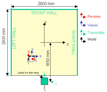
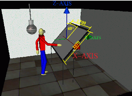
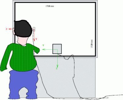
The workbench is operated by an SGI Onyx with one pipe. We configured a combination of two video channels each with the format 1024_768_96s. The managed area is 2048x768 with medium pixel depth. To the first video output we connected a normal monitor, to the second one the projector. Therefore the COVER window has its origin at [1024 0] (see section WindowConfig).
The dimension of the screen is 1700 mm x 1270 mm, and the screen is tilted 40 degrees.
The cycloop has two projectors, the passive stereo images can be either generated by one computer with two video channels or by two synchronised computers. In case of one computer the configuration of one large window with two viewports is preferable, because textures are loaded only once.
| Next |
| Authors: Martin Aumüller, Ruth Lang, Daniela Rainer, Jürgen Schulze-Döbold, Andreas Werner, Peter Wolf, Uwe Wössner |
| Copyright © 1993-2022 HLRS, 2004-2014 RRZK, 2005-2014 Visenso |
COVISE Version 2021.12
|