|
| Overview | All Modules | Tutorial | User's Guide | Programming Guide |
| Previous | COVISE Online Documentation | Next |
For volumetric scalar data, in addition to cutting planes and iso-surfaces, COVISE offers a direct volume rendering method based on texture hardware. This technique displays entire volume datasets. Transfer functions are used to determine the visual appearance of the datasets. The volume rendering functionality of COVISE was originally developed as part of the project VIRVO (Virtual Reality Volume Rendering) at HLRS.
Please note:
The Volume Rendering function has been provided as a preversion together with COVISE version 5.2. You gain additional functionality but you might encounter minor problems.
This chapter will give some basic information about volume rendering in COVISE. It will describe what types of volume data can be processed and how the user can display them.
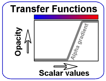
Since scalar volumetric data represent a solid 3D block of data values, the user needs a way to look inside of the block. A simple way to look inside is to clip the block along a plane, a more sophisticated method is to assign opacities to the data values. Opacity is the opposite of transparency: the higher the opacity, the lower the transparency. The assignment of opacity values to data values is defined by a transfer function. In addition to the transfer function for opacity, there is a transfer function that assigns colors to the scalar values. In Figure 5.1, both transfer functions are depicted: the opacity function is drawn as a line, the color function is represented as a color gradient. On the desktop, a ColorEdit module serves as a transfer function editor, the VR renderer COVER has its own built-in editor which comes with the Volume plugin and is displayed as soon as volume data is loaded.
Figure 5.1: Opacity and color transfer functions
Depending on the available graphics hardware, either 2D or 3D textures are used for displaying the volume data. If only 2D textures are supported, three sets of textures have to be stored in texture memory, one for each principal axis. For 3D textures the volume data only needs to be stored once. For technical reasons, on SGI machines each voxel occupies at least two bytes of texture memory, even if only 8 bits per voxel are stored.
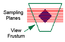
The volumes are displayed by drawing them slice by slice (see Figure 5.2). The number of slices drawn determines the rendering speed: the faster the graphics hardware, the more slices can be drawn and the higher the image quality. The slices are always oriented in a way that their normal vectors point towards the user, so that the user never looks in-between slices. The number of slices that can be drawn at interactive rates depends on the size of the volume object on screen. This is due to the pixel fill rate being the limiting factor.
Figure 5.2: Slicing approach for texture based volume rendering
In order to work with volumetric data, a dataset that is compatible to the volume rendering subsystem needs to be created. Compatible data must be located on a cartesian grid, which means that the coordinate axes must be perpendicular to each other, and the data values must be distributed equally on each coordinate axis. There can be different sample distances on each coordinate axis, but not within an axis. If the source data is not on a cartesian grid, it has to be resampled with the appropriate COVISE modules.
The total size of texture memory required for rendering can be computed by multiplying the number of voxels in each dimension with one another and with the number of byes per voxel. For example, a 16 bit per voxel dataset with 256 x 256 x 256 voxels requires 256x256x256x2 bytes = 32 megabytes of texture memory. If the data does not fit entirely into texture memory, it either has to be swapped in and out, which is time consuming, or it does not load at all. In the latter case, a white volume dataset is displayed.
Volume data in COVISE is internally represented as one of the following data types:
In COVISE, Volume data can either be computed at runtime, or it can be read from disk using the module ReadVolume. This module reads standardized VIRVO volume files, as well as sequences of 2D slice images. Volume files can be created by the module WriteVolume.
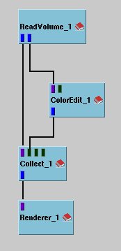
Figure 5.3 shows a typical COVISE network to read a volume file and display it in the renderer. It accepts several volume data types, and it can load a series of 2D images and merge them to a volume dataset. Files types are distinguished exclusively by the suffixes of their file names.
Figure 5.3: Map with ReadVolume to read volume datasets from disk
| File Extension | Description |
| rvf | Raw Volume File |
| xvf | Extended Volume File |
| avf | ASCII Volume File |
| tif, tiff | 3D TIF File (2D TIFF not supported) |
| dat | Raw volume data (no header) - automatic format detection |
| rgb | RGB image file (SGI 8 bit grayscale only) |
| pgm | Portable Graymap file (P5 binary only) |
| ppm | Portable Pixmap file (P6 binary only) |
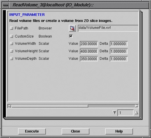
Figure 5.4 shows the ReadVolume Preferences window. The source file name must be set at the FilePath entry. If CustomSize is unchecked, the size entries are ignored and default values or the values from the respective volume file are used. Otherwise, the volume size will be set as entered in VolumeWidth, -Height, and -Depth.
Figure 5.4: ReadVolume Preferences window
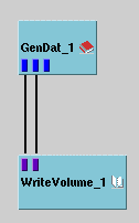
Figure 5.5 shows an example COVISE network to write volume data from GenDat.
Figure 5.5: Map with WriteVolume to write volume datasets to disk
| File Extension | Description |
| rvf | Raw Volume File |
| xvf | Extended Volume File |
| dat | Raw volume data (no header) - automatic format detection |
| pgm, ppm | Density or RGB images (depending on volume data type) |
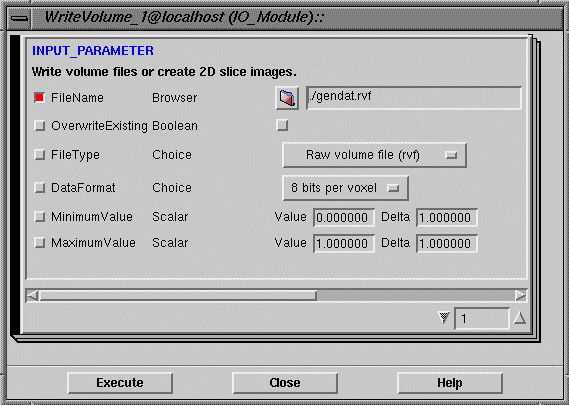
Figure 5.6 shows the preferences window of the module WriteVolume. The FileName entry expects the destination file name. If OverwriteExisting is checked, the destination file will be overwritten, if it previously existed. The file type and data format can be selected with the respective choice menus. MinimumValue und MaximumValue allow to constrain the stored data range. All values that are smaller or equal to MinimumValue will become zero, values greater or equal to MaximumValue will become 255 or 65535, depending on the data format (8 or 16 bit per voxel). The remaining values are distributed linearly inbetween.
Figure 5.6: WriteVolume Preferences window
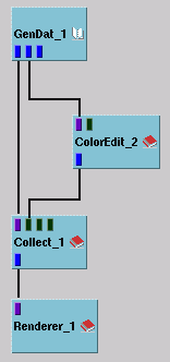
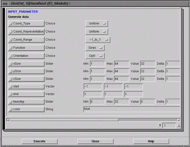
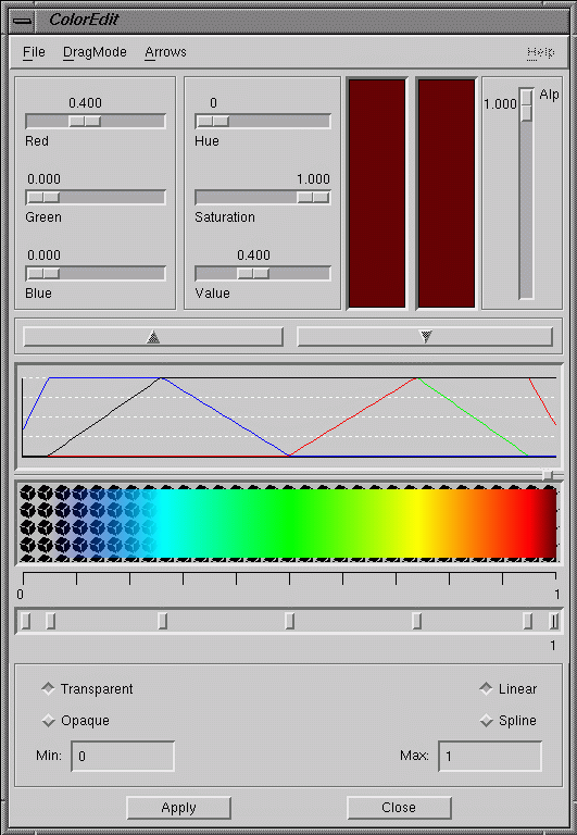
COVISE's desktop renderer displays volume data after they had been classified with the Color Editor module. A simple module layout can be created with the GenDat module (see Figure 5.7) as a uniform grid generator, when volume rendering compatible parameters (see Figure 5.8) are used. Both a uniform grid and scalar data are needed as data sources for volume data. The Color Editor (see Figure 5.9) acts as a transfer function editor. In order to get a volume display with semi-transparencies, the Transparency checkbox must be checked. The Color Editor module converts incoming scalar values to RGBA tuples, which are then passed on to the Collect module. The Collect module combines grid and data value information and feeds them into the renderer (see Figure 5.10).
Figure 5.7: Simple volume rendering map with GenDat
Figure 5.9: ColorEdit's color editor window
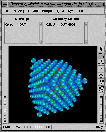
The desktop renderer offers a special draw style for volume data: while the data is rotated with the mouse, the volume is drawn in a lower quality to speed up the drawing process, and when the mouse button is released, the volume is drawn in regular quality. This draw mode ("move low volume") can be enabled in the pop-up menu which appears when the right mouse button is pressed in the renderer window.
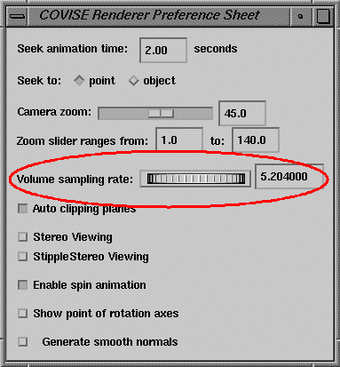
The quality of the static volume display can be set in the renderer's Preferences window (sampling rate, see encircled area in Figure 5.11). The Preferences window can be accessed from the renderer window's pop-up.
Figure 5.11: Desktop renderer's Preferences for volume quality
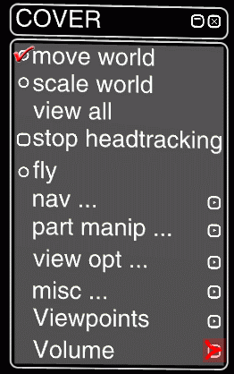
In order to work with volume data in the VR renderer COVER, the volume plugin must be loaded by adding the following line to the COVERConfig section of the covise.config file:
MODULE VolumePlugin
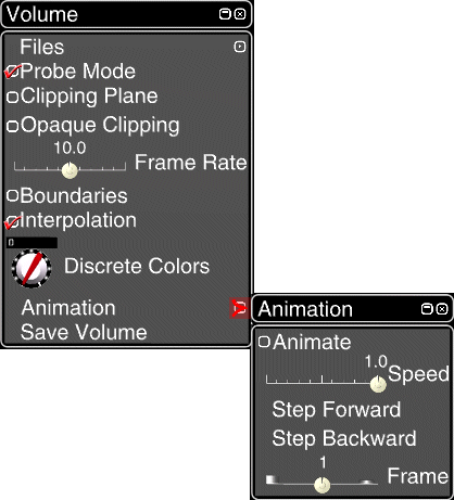
COVER's volume rendering capabilities can be accessed by the Volume menu (see Figure 5.12), which appears in the COVER main menu (see Figure 5.13) when the volume plugin was successfully loaded at startup. Its topmost entry is Files, which opens another menu with a selection of volume files. The file selection can be defined in the covise.config file in the VolumeFiles scope. Each line represents a file entry, consisting of a file path and a display name. These files can be created with the COVISE module WriteVolume, the supported file types are the same as for ReadVolume.
Figure 5.12: COVER Volume menu with Animation sub-menu
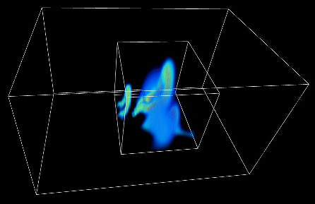
The Probe Mode checkbox toggles a mode in which only a cubic sub-volume is displayed (see Figure 5.16), which can be dragged around with the left mouse button and the size of which can be adjusted by twisting the mouse. Due to a smaller displayed region, a higher image quality is gained in the sub-volume.
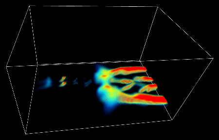
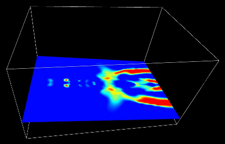
A clipping plane can be enabled by the Clipping Plane entry. By default the plane clips off the data on one side of the plane (see Figure 5.14), but it displays an opaque plane at the clipping location if Opaque Clipping is enabled (see Figure 5.15). To move the clipping plane, it has to be turned off and on again. The Clipping Plane checkbox enables or disables both clipping plane modes, the Opaque Clipping checkbox defines only the clipping type used.
With the Frame Rate slider, the Volume menu allows to set the rendering speed, which in turn affects display quality.
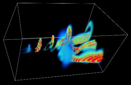
Figure 5.14: Lambda dataset with clipping plane
Another menu entry toggles a boundary box (see Figure 5.17) around the dataset. Yet another entry toggles data value interpolation (see Figure 5.18). By default, three-linear interpolation is used (if supported by the graphics hardware), when the interpolation is off, nearest neighbor interpolation is used for the volume display.
Figure 5.17: Lambda dataset with wireframe boundary box
The Animation menu can be used to control the display of time dependent datasets. If only a single time step is loaded, this menu has no effect. When Animate is checked, the time steps are cycled at the value selected by Speed. When the Speed slider is in the middle of its range, the speed is zero. The animation runs backwards if the slider is in the left half of its range. Step Forward and Backward can be used to switch to the next or previous time step respectively. The Frame slider can be used to directly access a specific time step.
When the Save Volume menu item is clicked on, the currently loaded volume dataset, together with the current transfer function, is stored to the file "virvo-saved.xvf", which is located in the directory which was current when COVER was started. The file can be read with ReadVolume, but only without the transfer function. When it is loaded directly from COVER's Volume Plugin by entering it into the list of files for the Files menu entry (in covise.config), the saved transfer function will be restored.
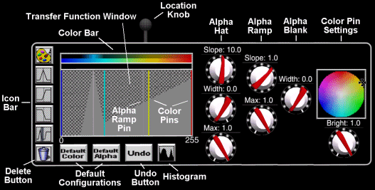
As soon as a volume is loaded from the menu, the transfer function editor window pops up (see Figure 5.19). The transfer function for opacity can be combined by a number of different elements: a tent function, a ramp, and an alpha blank. In the transfer function window, the elements can be accessed by Pins, which are represented as vertical lines. These lines can be moved horizontally. For each scalar value, the maximum value of the alpha function's components define the current transfer function. Alpha blanks dominate over all other alpha Pins, they set the alpha value to transparency no matter what other elements are located at the same position.
Figure 5.19: Transfer function editor in three different interaction states
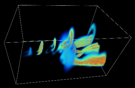
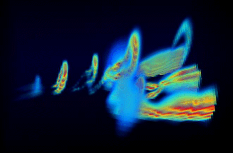
Figure 5.20: Low quality Lambda dataset
DAT: Pure volume data file
This file type stores raw volume data without a header. The data can contain 1,2,3, or 4 byte per voxel. When loading a file of this type, the program tries to find the volume dimensions automatically. If this doesn't work, you can help by adding the volume size to the file name prefix, for instance "cthead256x256x64.dat" for a 256 x 256 x 64 voxels dataset.
The order of voxels in the file is: start at top-left-front, go right first, then down, then back (just like the order of letters in a book). All bytes of each voxel are stored consecutively, beginning with the most significant byte for 8 and 16 bit per voxel files, or in RGB(A) order for 24 and 32 bit per voxel files. DAT files can only store one time step.
RVF: Raw volume file
This format can easily be created by hand from any voxel data array on disk by adding the appropriate header: 3 x 2 Bytes (big endian) for the volume's width, height, and depth in voxels. This can be done with a hex editor, for example. The header of a 256x128x127 volume would be (hex values): 01 00 00 80 00 7F The volume data can only have 8 bit per voxel in RVF files, and only one time step can be stored. The data order is the same as in DAT files.
XVF: Extended volume file
This format can store more information than DAT and RVF, but it is still easy enough to describe and to create manually. XVF files can store multiple volume datasets (time steps) in one file, and the storage of a random number of transfer functions. 8 to 32 bit can be stored per voxel. In order to create an XVF file manually, it is important to know that the byte order of integer values is big endian (most significant first), floating point values are stored in big endian mode and 4 byte IEEE standard. In this standard, the hexadecimal representation of 1.0 is: 3F 80 00 00. Here is the XVF header specification:
XVF Header:
| Length | Data Type | Description |
| 9 bytes | char | file ID string: "VIRVO-XVF" |
| 2 bytes | unsigned short | offset to beginning of data area, from top of file [bytes] |
| 2 x 4 bytes | unsigned int | width and height of volume [voxels] |
| 4 bytes | unsigned int | number of slices per time step |
| 4 bytes | unsigned int | number of frames in volume animation (time steps) |
| 1 byte | unsigned char | bits per voxel (supported values: 8, 16, 24, 32) |
| 3 x 4 bytes | float | real world voxel size (width, height, depth) [mm] |
| 4 bytes | float | length of a time step in the volume animation [seconds] |
| 2 x 4 bytes | float | physical data range covered by voxel data (minimum, maximum) |
| 3 x 4 bytes | float | real world location of volume center (x,y,z) [mm] |
| 1 byte | unsigned char | compression type (0=none, not supported yet) |
| 2 bytes | unsigned short | number of transfer functions |
| 2 bytes | unsigned short | type of transfer functions: 0 = 4 x 256 Byte for RGBA channels (deprecated) 1 = list of control pins |
Data area:
The data starts at the position "offset to beginning of data area" (see table). The voxel order is similar to DAT and RVF files, all bytes of each voxel are stored consecutively. If multiple time steps are stored, they follow one by one, with no separator inbetween.
Transfer functions:
The transfer functions are stored at the end of the file, right after the data area. Transfer functions should not be added to the file manually, this should only be done from within COVISE (currently this is only supported by the "save volume" function in COVER). Therefore, the format of transfer functions will not be described here. To create a volume file manually, it is sufficient to set the number of transfer functions to zero in the header.
AVF: ASCII volume file
AVF files are ASCII representations of volume data. They consist of a header and a data section:
Header:
In the header, several lines give information about the data format. Each line consists of an identifier and a value, separated by whitespace. Each line can contain one identifier and one value. This file format cannot store transfer functions. Anywhere in the file, comments starting with '#' are allowed. This comments out all the rest of the line.
The following abbreviations are used:
<int> = integer values
<float> = floating point values
<OPT1|OPT2|OPT3> = list of options
The following lines are required:
| WIDTH [int] | width of the volume [voxels] |
| HEIGHT [int] | height of the volume [voxels] |
| SLICES [int] | number of slices in the volume [voxels] |
The following lines are optional. If they are missing, the respective default values are used:
| FRAMES [int] | number of data sets contained in the file (default: 1) |
| MIN [float] | minimum data value, smaller values are constrained to this value (default: 0.0) |
| MAX [float] | maximum data value, larger values are constrained to this value (default: 1.0) |
| FORMAT [SCALAR8/16 or RGB(A)] | voxel data format (default: SCALAR8): SCALAR8 = scalar values, to be stored as 8 bit integers SCALAR16 = scalar values, to be stored as 16 bit integers RGB = color values, consisting of a red, a green, and a blue color component, stored as 3x8 bit RGBA = color values, consisting of a red, a green, a blue, and an opacity (alpha) value, stored as 4x8 bit |
| XDIST [float] | the sample distance in x direction (width) [mm] (default: 1.0) |
| YDIST [float] | the sample distance in y direction (height) [mm] (default: 1.0) |
| ZDIST [float] | the sample distance in z direction (slices) [mm] (default: 1.0) |
| TIME [float] | the length of each time step for transient data [s] (default: 1.0) |
Data area:
The data area begins right after the header. The voxel data values are listed, separated by whitespace and/or end-of-line markers. Both floating point and integer values are accepted. The voxel order is similar to DAT, RVF, and XVF files. All elements of each voxel are stored consecutively.
Sample file:
WIDTH 4
HEIGHT 3
SLICES 2
FRAMES 1
MIN 0.0
MAX 1.0
FORMAT SCALAR8 # 8 bit data
XDIST 1.0
YDIST 1.0
ZDIST 1.0
TIME 1.0
0.9 0.9 0.9 0.9
0.9 0.2 0.3 0.9
0.9 0.2 0.4 0.9
0.8 0.8 0.8 0.8
0.8 0.1 0.1 0.8
0.8 0.0 0.0 0.8
The lambda function dataset used in some images is courtesy of Ulrich Rist, IAG, University of Stuttgart.
| Previous | Next |
| Authors: Martin Aumüller, Ruth Lang, Daniela Rainer, Jürgen Schulze-Döbold, Andreas Werner, Peter Wolf, Uwe Wössner |
| Copyright © 1993-2022 HLRS, 2004-2014 RRZK, 2005-2014 Visenso |
COVISE Version 2021.12
|