|
|
| Overview | All Modules | Tutorial | User's Guide | Programming Guide |
| Previous | COVISE Online Documentation | Next |
After having read this chapter you will be familiar with:
In the previous chapter you have read about some basic steps in working with COVISE. You have already learned how to load a prepared module network. In this chapter we introduce some functionalities of the OpenInventor Renderer and their main usages. COVISE comprises other render modules as well but the OpenInventor Renderer can be seen as the default desktop renderer. OpenInventor is a high level object oriented graphics toolkit developed by Silicon Graphics. It uses OpenGL, the 3D graphics standard, as its rendering interface.
You can regard the Renderer as a movable window to a virtual world. The displayed scenario contains objects which are typically visual representations of simulation data. Depending on the selected visualization method you can have different visual representations for the same dataset. This allows to explore the various aspects and characteristics of a dataset and detect features otherwise not seen. In addition to the mapping of data to visual representations supportive geometries, such as bounding surfaces or reference geometries of machineries provided via CAD models can also be included in combination with the data visualizations. A typical example would be the visualization of a pressure distribution in a combustion chamber of a car engine. Such scenarios can be further examined with all the possibilities that the Renderer provides.
Figure 2.1 : The Renderer Module Icon
The module selection and the usage of ports to build module networks will be described in the following chapters
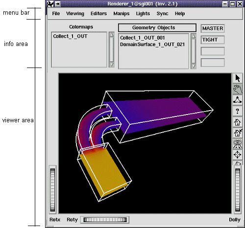
In Figure 2.2 you can see the OpenInventor Renderer as it will appear on your desktop after you have inserted the Renderer module in the module placing area.
The renderer window consists of three major parts:
The menubar will only be explained shortly. It provides functionalities such as saving the current scene to a file or printing the scene. You can also adjust viewing parameters or set material and light properties using the menus. The information area provides information about the current state of the renderer. Beside some text fields for collaboration status there are two list boxes. The ColorMaps list box contains all the colormaps used in the visualization pipeline. The GeometryObjects list box contains all the geometry objects currently displayed. The viewer area holds the main viewer widget where the objects are displayed. The viewer area contains also other user interface elements.
Figure 2.2: The Renderer User Interface
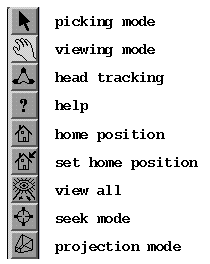
Figure 2.3: The Toolbar
Pressing the seek mode button changes the cursor to the seek mode symbol. Within this mode you can click on any part of your geometry. This will set the camera position in a way, that the selected point will be in the center of the window with a view orientation orthogonal to the object.
The button on the bottom of the toolbar selects a projection mode. By pressing this button you can switch between a perspective and an orthogonal projection. The default projection mode is the perspective one.
Arranged at the bottom of the viewer area are some user interface elements for rotating and zooming the camera. On the left side are two thumb wheels to rotate the camera about the x (Rotx) and the y (Roty) axis.
On the right side is a slider (Zoom) and a thumb wheel (Dolly) to zoom the camera.
The OpenInventor Renderer knows two fundamental interaction modes of the mouse:
By clicking with the right mouse button into the viewer area in any of the two interaction modes a popup menu appears. This popup menu will not be further explained here. It provides many functionalities you find on the menubar too.
| Previous | Next |
| Authors: Martin Aumüller, Ruth Lang, Daniela Rainer, Jürgen Schulze-Döbold, Andreas Werner, Peter Wolf, Uwe Wössner |
| Copyright © 1993-2022 HLRS, 2004-2014 RRZK, 2005-2014 Visenso |
COVISE Version 2021.12
|