![[*]](crossref.png)
| Overview | All Modules | Tutorial | User's Guide | Programming Guide |
| Previous | COVISE Online Documentation | Next |
In this chapter the main functionality of the COVISE Renderer is summarized. Like the map editor, one renderer is started on every host in a cooperative working session, once the master renderer has been brought up on the master map editor.
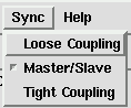
The design of the Renderer supports collaborative working (for more details see chapter 5, COVISE CE - Collaborative Working): Basically the Renderer works in a "what you see is what I see" mode. This is called the Master/Slave Mode or Tight Coupling. It means, that every partner in the session has the same viewpoint in respect to the rendered geometry objects. Only the master has the ability to change the view in the other renderers. On the slave side it is possible to change the camera position independently from the others as long as the master isn't changing anything. As soon as the master performs an interaction, the slaves automatically become synchronized and updated. (Strictly speaking, there is a slight difference between "Master/Slave Mode" and "Tight Coupling": "Master/Slave" causes the slave renderer to be updated at the end of a move only, whereas "Tight" makes a contiuous update. The two possibilities have been introduced due to performance considerations.)
Alternatively, the master has the ability to switch to a second mode called Loose Coupled Mode. When this mode is enabled, every partner has full access to all Renderer functionalities without disturbing the other partners setup and view. This mode is convenient when the partners have stopped their discussion about the current rendered objects and want to do some postprocessing on the data, like changing some colors, adding light sources, saving or printing etc..
The discussion on the data is supported by introducing Telepointers. A telepointer marks a position in the renderer's window to guide the other partners to interesting details on the screen. Each renderer has a telepointer attached to the current mouse position, which is sent to the remote renderers.
In addition, the renderer supports stereo viewing mode with the Crystal Eyes shutter glasses as well as with various autostereoscopic viewing devices. It also supports the Spaceball or the DLR Spacemouse for 6Degree of Freedom interaction.
is displayed in the MapEditor canvas and the renderer main window appears on the
screen as shown in .
![]()
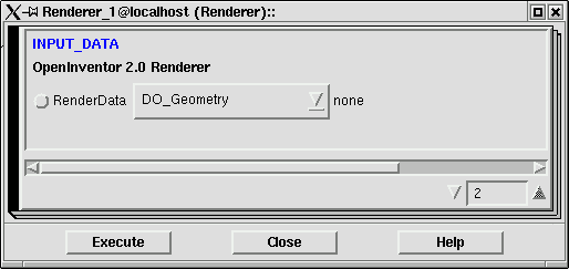
Note that you can resize the renderer according to your needs, but reducing the
window size may hide some of the menu components. By clicking on the module setup
button in the Renderer icon, the data object and parameter list for the Renderer
appears ().
As you can see, no parameters can be set or adjusted, and there is currently only one input port called DO_Geometry. In the future there may be additional input ports, e.g. for pixel images. Unlike other application modules in the COVISE environment, the renderer has it's own Motif based point and click user interface. You can connect all modules with geometry output ports to the renderer's input port. The renderer will accept any number of input objects. After an execution of a complete module network, the renderer will appear highlighted while new objects from local memory or remote machines are sent into the module. New rendered objects will be shown in the geometry objects list in full name. You can find out your point of view in respect to the scene by looking at the coordinate axes and their orientation. If you cannot see objects just select the View All icon on the right side of the drawing area.
You see the objects as you would look through a camera lens. While pressing the left mouse button and dragging the mouse around in the Viewer Area, you can move the camera around the scene. This allows you to rotate the whole view around a point of interest using a virtual trackball. The viewer area uses the camera's focal distance to figure out the point of rotation, which is usually set to be in the center of the scene. You can also translate the camera in the viewer plane by using the middle mouse button as well as zoom (getting closer or moving backward from the scene center) by using both left and middle mouse buttons. The viewer area also supports seeking (see description of viewer pop-up and decoration). You can also use the decoration thumb wheels around the viewer area for most of these operations. Changing the camera means changing the view in respect to all visible objects. If you want to do editing operations like scaling certain objects or changing some colors, you need to switch to the Edit Mode (or Pick Mode) first. Therefore, press the Pick Mode icon on the right side of the viewer area. The cursor changes to an arrow shape and you can select objects now by clicking on them with the left mouse button. A wireframe bounding box appears around the selected object and the name of the object gets highlighted in the geometry object list. Now it is possible to edit this object by bringing up multiple manipulators and editors, all explained in detail in the next sections. If you want to return in viewing mode click on the View Mode icon. Note that editing operations are only possible in master mode. Only the master has access to the menu bar functionality. For the slave renderers the menu bar is disabled.
see Chapter 5, COVISE CE, section MasterCtrl, subsection Synchronization
see Chapter 5, COVISE CE, section MasterCtrl, subsection Telepointer
In the following sections the components of the renderer user interface are discussed.
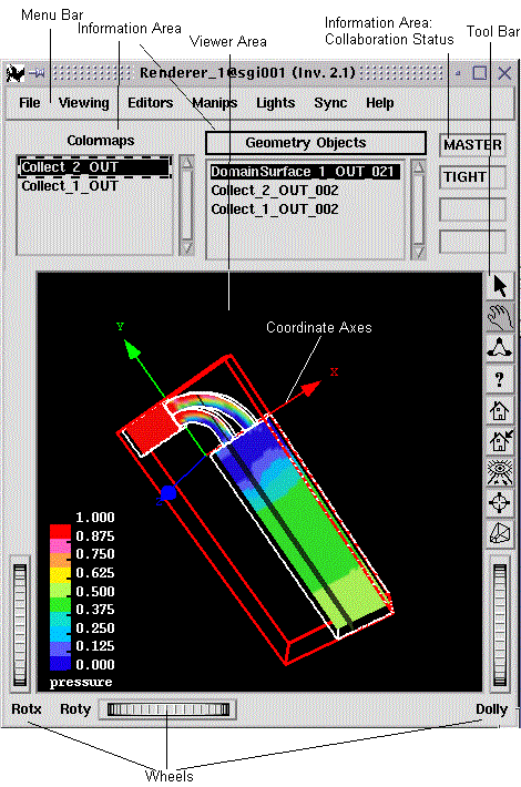
In the viewer area objects are displayed and can be manipulated in several ways. The coordinate axes show the current view orientation.
Using the mouse buttons in viewing mode affects the camera position, the line of sight, and the angle of vision in respect to the scene. In the default viewing mode, the mouse buttons have the functionality as described earlier. In edit (pick) mode, pressing the left mouse button selects the object under the mouse cursor. When seeking is enabled by clicking on the seek icon, pressing the left mouse button starts seeking to the selected point.
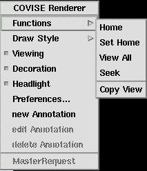
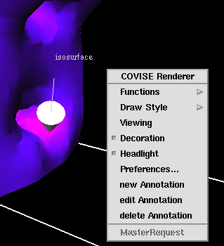
The popup menu () is activated by clicking the right mouse button while
the mouse pointer is positioned in the viewer area. The popup menu contains
several items and sub menus. These are:
The last three items of the drawstyle sub menu in the viewer popup menu activate single buffering, double buffering or the switching between single buffering during manipulation and double buffering otherwise.
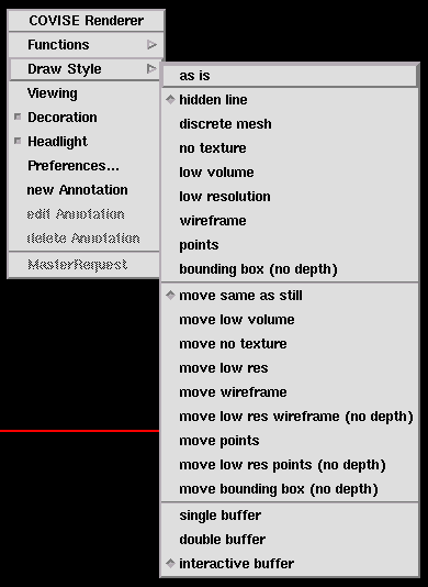
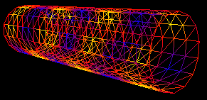
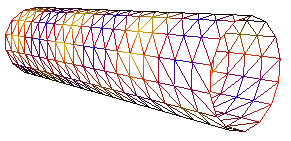
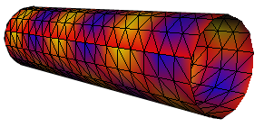
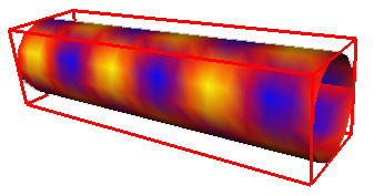
You can see different viewing modes in , , and . The
hidden line representation removes all lines which normally could be seen
shining through in a wireframe representation.
).
When you click on the background in the viewer area the object becomes deselected again. You can only select one object at a time.
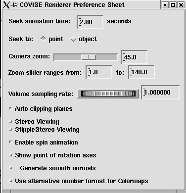
A menu appears in which defaults for the seek mode, zoom slider bounds, clipping
planes and stereo viewing can be set, or an alternative number format for colormaps can
be specified:
This field can be used to specify formats of the numbers along the
color legend. It must be a float format for the "printf" format as
specified in the unix manual pages and should be left-justified.
Examples: Values 0 0.1 0.2 0.3 0.4 0.5

Format: %-.3f   -->   0.000 0.100 0.200 0.300 0.400 0.500
        %-.2f   -->   0.00 0.10 0.20 0.30 0.40 0.50
The Volume sample rate thumbwheel is needed for
Volume Rendering (see Appendix).
When Spin Animation is enabled, objects can be rotated around in an animated fashion in viewer mode.
Switch to pick mode and click on the detail you want to explain: You can now (using a popup with "apply")
Please note:
The decoration consists of three thumb wheels for rotating (Rotx, Roty) and zooming (Dolly) as well as a zoom slider trim (Zoom) and six viewer icons to the right side of the viewer area. These icons are shortcuts for some of the viewer pop-up functionality. From top to bottom there are icons for
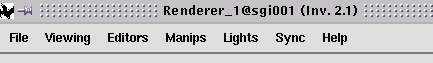
The menu bar of the renderer window is shown below.
pict/mediaconvert.png
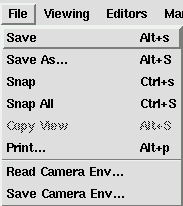
The viewing menu is shown in .
By default the renderer is in the View mode. The viewer uses a virtual trackball to rotate the scene graph around the point of interest. If you want to change the view of a scene but a specific object in respect to other objects, you have to switch from the View mode to Pick/Edit mode. In Edit mode the outlined hand cursor changes to an arrow shape cursor. If you click on an object with the left mouse button, the object becomes selected and highlighted by a red wireframe box which now surrounds the object. You can select only one object at a time. If you have opened any editors or enabled manipulators, these will be attached to the selected target object for further editing. If you switch between objects by clicking on a different object all manipulators and editors automatically become attached to this object.
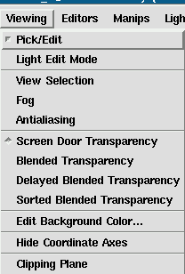
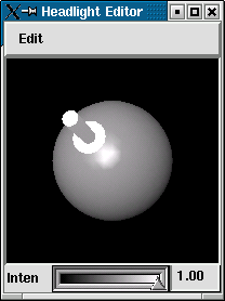
Enabling this mode lets you interactively edit the current visible light sources in the scene by using the mouse.
This item affects the environment of a scene to simulate various atmospheric effects such as fog, haze, pollution and smoke which are grouped under the term fog.
This technique is useful to eliminate or reduce jagged lines and make objects drawn on the screen look smooth. Enabling this item reduces drawing speed.
This and the next three items affect the transparency quality level. Screen door transparency is the default and the only supported mode on some machines. For transparency details refer to the editor's section. Screen door transparency uses GL patterns for achieving the transparency effect.
uses GL alpha blending.
uses GL alpha blending, opaque objects are rendered first, then transparent objects.
uses GL alpha blending, opaque objects are drawn first, then transparent objects. Additionally the objects are sorted by their distance from the camera and are drawn from back to the front.
Invokes a color editor for changing the background color of the render area (default is black).
Toggles between hiding and showing the three coordinate axes. The axes are on by default.
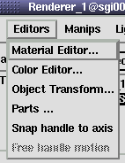
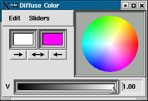
The material editor is used for customizing objects by interactively changing values for ambient, diffuse, specular, transparent, emissive and shininess elements and immediately seeing the effects of these changes.
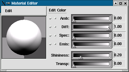
The diffuse color is the object's base color specified in the color array of the renderer geometry input data objects. If no colors are specified, the color of each vertex of the object is set to RGB [1.0 1.0 1.0] default. Editing the diffuse color of those objects affects all vertices of the object, thus the whole object changes its color. If one color is specified for the whole object (color binding OVERALL) all vertices of the object are colored according to this value. If you edit the diffuse color of these objects, also all vertices are affected by color changes. If vertex based objects such as polygons or lines with colors attached per vertex (color binding PER_VERTEX) or per face (binding PER_FACE) are present, only the first vertex is affected by changes of the diffuse color field, therefore editing the diffuse color of those objects is not very useful. The next items affect the whole object in any case. The Ambient Color is the reflected color of an object in response to the ambient lighting in the scene. The default value for this field is [0.2 0.2 0.2]. The Emissive Color is the light caused by self illuminating objects. The default for this field is [0.0 0.0 0.0], which means the object is emitting no light. The degree of shininess of an object's surface is for e.g. achieving metallic effects on the surface of an airplane wing. The value ranges from 0.0 (default) for a diffuse surface with no shininess to 1.0 for a highly polished surface. Let us assume there are two objects present by one object covering the other, where one cannot see the covered object. By adjusting the Transparency Level of the covering object you can see either both (values larger than 0.0) or only the previously covered object (value 1.0).
The color editor lets you interactively change the color properties of an object, a light source or the background color of the render area. You can set RGB or HSV values or pick a color directly from the color wheel. By selecting Manual from the edit menu bar item you can prevent changes being reflected immediately in the object until you are ready. Use the two color squares to test new colors and store the previous one. By clicking on the three pads beneath the squares, you can switch back and forth between colors. The new color is always on the left and the previous color on the right. You can send the new color to the right square, or the old color to the left square. RGB values range from 0.0 to 1.0 for the red, green and blue color component, where [0.0 0.0 0.0] is black and [1.0 1.0 1.0] is white.
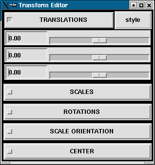
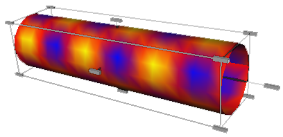
Transform sliders are useful to change the position of objects in respect to each other or to scale an object to make it appear larger or smaller on the screen. If you click on an item in the transform slider set sub menus appear in which you can do the desired editing operations by adjusting sliders with the mouse or typing exact values using input fields. There are three different widget layout styles available, simply click on Style in the slider menu. Note that the changes only affect the currently selected object in the scene. Translation changes the position of an object in the scene. Scale changes the size of an object. Rotation changes the orientation of the object in the scene. Scale Orientation changes the orientation for scale operations. Center changes the center around which rotations take place.
If the geometry objects displayed by the Renderer can be identified (in case of modules using finite elements) you can use the COVISE Part Editor to select which parts of the geometry will become visible or invisible and, optionally, which part is fixed during movements.
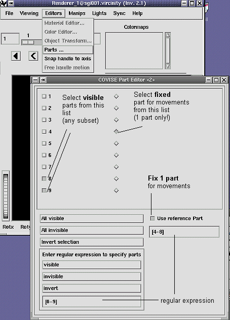
The left side of the Part Editor window provides the functions to select which parts are visible; you have 3 possibilities:
On the right side you can (optionally) select a reference part that will be fixed during movements; to specify this reference part you can use 2 possibilities:
The last two options of the Editors menu item have been added to select options for an Interactor. If you want to move e.g. a Cutting Surface, you can attach an interactor to it. An interactor attached to a point of a Cutting Surface consists of
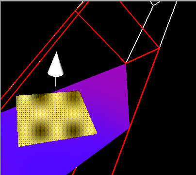
You attach an interactor by clicking on a point of the Cutting Surface.
Note: You must be in pick mode and select (click on) the Cutting Surface before you can attach an interactor
You can
You use the option
Manipulators are used for direct manipulation of a certain object, like the editors explained in the last section.
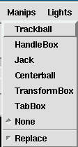
This way of manipulation is more direct than using editors, but less precise
than using the sliders. To attach a manipulator to an object, switch to the
picking mode and select a manipulator type in the Manips Menu shown in .
Now click on the desired object. The manipulator appears and surrounds the object. There are different manipulators to transform, rotate, scale, and move an object in the viewer.
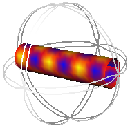
This manipulator is for rotating and scaling an object. It appears as a transparent sphere around the selected object.
)
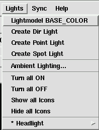
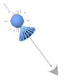
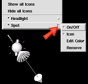
The lights menu is for creating, editing, and removing light sources in an object scene. This is a feature used for changing the appearance of an object by changing its illumination. Light information is currently not sent to other renderers in a cooperative working environment. Each entry in the menu is explained now in detail.
see Chapter 5, COVISE CE, section MasterCtrl, subsection Synchronization
Pressing Help provides you online help for the Renderer - but you can easily branch e.g. to help for MapEditor or Modules.
On the left side of the information area, the list of currently displayed geometry objects is shown (together with the colormaps used).
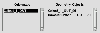
If you click on a certain object in the render area the name of the object gets highlighted in the object list. It is also possible to select an object in the render area by clicking on it's name in the object list. The red bounding box appears around the selected object in the render area to highlight the selection. Thus, similar objects can be distinguished by their unique name.
On the right side of the information area there are four lines; the first two display the collaboration status of the renderer:
If the Spaceball or the DLR Spacemouse is connected to your workstation, you are able to manipulate the geometry objects in 3D space in a six degrees of freedom fashion. The device should beep two times at renderer startup time when initialization of the device was successful. To move an object around select the object in picking mode. The device is now attached to the selected object. Some of the device buttons provide some additional functionality:
If no object is selected, the spacemouse changes the viewpoint in respect to the scene by changing the current camera position.
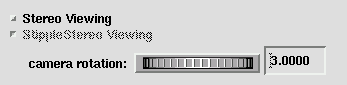 Some platforms support stereo in a window viewing. Stereo viewing is enabled
by choosing Stereo Viewing in the renderer's preference sheet. You return to
the default mode by deselecting Stereo Viewing in the preference sheet or
typing in a shell window:
Some platforms support stereo in a window viewing. Stereo viewing is enabled
by choosing Stereo Viewing in the renderer's preference sheet. You return to
the default mode by deselecting Stereo Viewing in the preference sheet or
typing in a shell window:
/usr/gfx/setmon -n 72HZ or /usr/gfx/setmon -n 60HZ depending on the type of monitor attached.
currently not implemented
| Previous | Next |
| Authors: Martin Aumüller, Ruth Lang, Daniela Rainer, Jürgen Schulze-Döbold, Andreas Werner, Peter Wolf, Uwe Wössner |
| Copyright © 1993-2022 HLRS, 2004-2014 RRZK, 2005-2014 Visenso |
COVISE Version 2021.12
|