| Overview | All Modules | Tutorial | User's Guide | Programming Guide |
Module category: Tools
Transform manipulates grids and geometry objects. Transform makes it possible to mirror, translate, scale, rotate and tile objects and their data.
Transform is available for COVISE version 4.5 and higher. It's available for all supported platforms.
Note that the reader may override the values of the parameters below, if he gets a geometry object (first port) with the attribute TRANSFORM. If this is the case, the module expects for each parameter whose value should be overridden a subchain with the following structure: first comes the parameter name, and, separeted by a blank, another chain indicating the value to be used. If several parameters are overridden, these subchains are separated by newline characters. As for the subchain indicating the value, it is always made out of numbers, even for boolean and choice parameters, which may be several and separated by blanks in the case of vector parameters.
Transform: Mirror
| Name | Type | Description |
| normal_of_mirror_plane | Vector | Normal of the mirror plane. |
| distance_to_origin | Scalar | Distance to origin. |
| MirroredAndOriginal | Boolean | It determines whether the original model is also included in the output or only the mirrored geometry. |
Transform: Translate
| Name | Type | Description |
| vector_of_translation | Vector | Every object is translated by this vector. |
Transform: Rotate
| Name | Type | Description |
| axis_of_rotation | Vector | Direction of the axis. |
| one_point_on_the_axis | Vector | One point on the axis. |
| angle_of_rotation | Scalar | Angle in degrees. |
Transform: Scale
| Name | Type | Description |
| scaling_factor | Scalar | Scaling factor. |
| new_origin | Vector | The object is translated by this vector. |
Transform: MultiRotate
| Name | Type | Description |
| axis_of_(multi-)_rotation | Vector | Direction of the axis. |
| _one_point_on_the_axis | Vector | One point on the axis. |
| angle_of_(multi-)rotation | Scalar | Angle in degrees. |
| number_of_rotations | Scalar | Number of rotations. |
Transform: Tile
| Name | Type | Description |
| TilingPlane | Choice | Tiling plane: XY, YZ or ZX. |
| flipTile | Boolean | It indicates whether the tiles are obtained by flipping the original model (combinations of reflections) or just by simple translation. |
| TilingMin | Vector | It describes the position of the tile with the smallest coordinate values. |
| TilingMax | Vector | It describes the position of the tile with the largest coordinate values. |
Transform: Other parameters
| Name | Type | Description |
| InDataType_0...3 | Choice | Magnitude options:
TrueVectorOrScalar, PseudoVectorOrScalar, Displacements. |
| createSet | Boolean | Its value is only relevant in the case of
transformations that would create multiple objects for each input object.
This is namely the default behaviour in the case of tiling and multirotations,
and mirroring too, when the original geometry is also to be displayed. Sometimes this default behaviour might cause performance problems if the name of element objects in the output sets is too large. In this case, you may try setting this parameter to false, and all these output objects shall be gathered in a single object, provided that it is an unstructured one: Points, Lines, Polygons, TriangStrips, UnstructuredGrid, Float or Float |
With these parameters you may declare the nature of the magnitudes you are transforming. In the pseudovector or pseudoscalar case, the output field flips sign with respect to the output using the first option if the jacobian of the transformation is negative. The third case, Displacements, is only meaningful when you are tiling the model; the output is the correct continuation of the input vector field if it has the meaning of displacements.
| Name | Type | Description |
| requiredgeo_in |
Polygons TriangleStrips Lines Points UnstructuredGrid UniformGrid RectilinearGrid StructuredGrid | Grid or geometry objects. |
| optionaldata_in0 ... data_in3 |
Float Vec3 Float Vec3 | Scalar or vector data. |
| Name | Type | Description |
| outputgeo_out |
Polygons TriangleStrips Lines Points UnstructuredGrid UniformGrid RectilinearGrid StructuredGrid | Transformed objects. |
| dependdata_out0 ... data_out3 |
Float Vec3 Float Vec3 | Scalar or vector data on the transformed objects. |
|
|
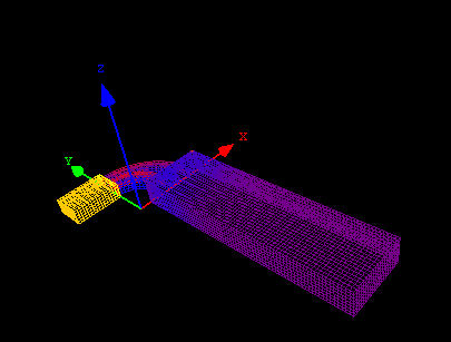
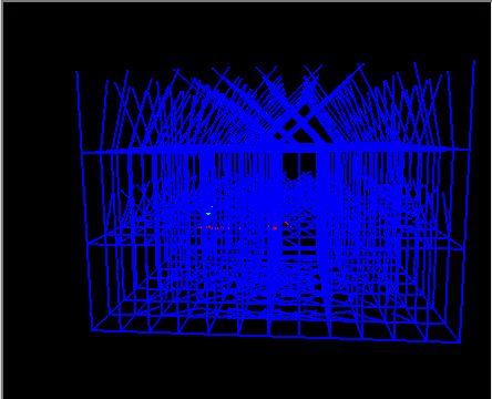
Suppose we have a symmetrical object.
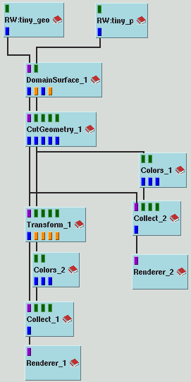
We use Transform in the map covise/net/examples/Transform.net to construct the whole object.
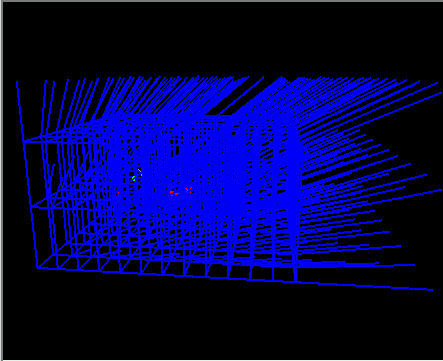
RWCovise_1 reads in the computational grid of a channel with two inlets. RWCovise_2 reads in the data on the surface. DomainSurface computes the outer surface of the channel. CutGeometry cuts away one half of the channel. You can see the result in Renderer2. The first figure shows you a screenshot of the original (half) object with wireframes. Transform mirrors the object and its data. The mirror plane is described by the normal vector (0,0,1). The origin is on the mirror plane. Colors translates the data into colors.
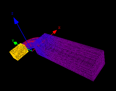
The second figure shows the whole channel in the renderer. Both the original non-mirrored and mirrored geometries are shown because the value of parameter MirroredAndOriginal is true.
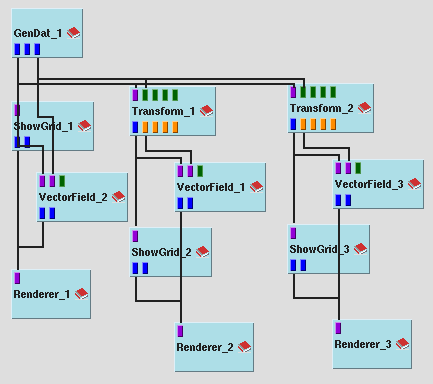
In the next example we illustrate the use of tiling. In this case we are using the flipping option. The first renderer snapshot shows the effect on a normal vector field. Note that we perform the tiling by mirroring. The second image shows the result if the input vector field is assumed to be a field of displacements.
| Authors: Martin Aumüller, Ruth Lang, Daniela Rainer, Jürgen Schulze-Döbold, Andreas Werner, Peter Wolf, Uwe Wössner |
| Copyright © 1993-2022 HLRS, 2004-2014 RRZK, 2005-2014 Visenso |
COVISE Version 2021.12
|