| Overview | All Modules | Tutorial | User's Guide | Programming Guide |
Module category: Mapper
The IsoSurface module creates an isosurface from a three dimensional structured or unstructured grid-based data set using the marching cubes algorithm. Optionally given data input can be mapped on the generated surface using interpolation. Each input port also accepts Sets of the appropriate types.
IsoSurface has been tested on SGI, NEC SX4 and HP platforms.
| Name | Type | Description |
| gennormals | Boolean | Generation of surface normals. Since renderers often have problems generating normals on the fly, this option is recommended and TRUE by default. |
| genstrips | Boolean | Generation of triangle strips. This option can be used to take advantage of graphics hardware in the final rendering steps. Default is TRUE. |
| isopoint | Vector | Point determining the isosurface. |
| isovalue | Boolean | The isovalue to be extracted from the data set. The default value is 0.0. |
| autominmax | Boolean | - |
|
|
| Name | Type | Description |
| requiredmeshIn | UniformGrid RectilinearGrid StructuredGrid UnstructuredGrid | All kinds of grid-based data is accepted as input including sets. |
| requiredisoDataIn | Float Float | Scalar or vector data is accepted as input for isosurface generation. The number of elements (or vertices) must match that of the respective grid. |
| optionaldataIn | Float Float Vec3 Vec3 | This optional port can be used to map additional values onto the created isosurface for coloring. |
|
|
| Name | Type | Description |
| outputmeshOut | Polygons TriangleStrips | IsoSurface produced in either polygonal or optimized triangle strip format. |
| outputdataOut | Float Vec3 | Interpolated data on the surface, when data has been provided at the optional input port dataIn. |
| outputnormalOut | Unstructured_V3D_Normals | Normals calculated based on the weighted average of the face normals of all neighbor faces of the resulting polygonal isosurface. Normal generation turned on results in a higher memory consumption of the isosurface module. |
|
|
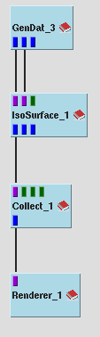
The first example network shows an isosurface generation using data from the GenDat module. The meshIn port of the IsoSurface module is connected to the meshOut port of the GenDat module. The isoDataIn is connected to the scalar data output port of GenDat. Only the meshOut port of the IsoSurface module has been connected to the Collect module in this example to test the normal generation feature of the Inventor renderer. It is recommended to use the normal output of the isosurface module in normal cases.
You find the map in the directory covise/net/general/examples.
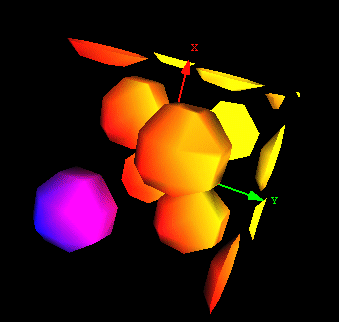
The next image is a snapshot of the results in the Inventor Renderer.
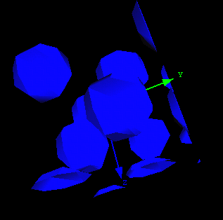
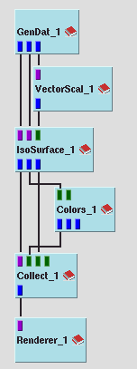
The next two images show a slightly more complicated example (IsoSurface2.net) and the corresponding renderer output.
In this case, the module terminates execution, submits a message, increases the ratio by 5% and re-executes itself. To prevent this procedure, establish a higher starting value by putting a section with a higher value (e.g. 50%) into your covise.config:
IsoSurface
{
   # Ratio of array size to number of input vertices in Percent
   VERTEX_RATIO   50
}
This value is used by both IsoSurface and IsoSurfaceP. The theoretical maximum value is 300% (VERTEX_RATIO 300).
| Authors: Martin Aumüller, Ruth Lang, Daniela Rainer, Jürgen Schulze-Döbold, Andreas Werner, Peter Wolf, Uwe Wössner |
| Copyright © 1993-2022 HLRS, 2004-2014 RRZK, 2005-2014 Visenso |
COVISE Version 2021.12
|