| Overview | All Modules | Tutorial | User's Guide | Programming Guide |
Module category: Mapper
The only difference between CuttingSurface and CuttingSurfaceComp is that CuttingSurfaceComp directly produces its output for a Renderer. To get a colored output you have the possibility to pass a colormap by an input port. In general you will only connect the first output port of the module directly with the renderer. Using this module instead of CuttingSurface reduces the number of modules (Collect, Colors, VectorField...) you have to use.
CuttingSurfaceComp implements now the functionality of CuttingSurface3DTex, which should no longer be used. More remarks to this point are found under examples.
CuttingSurfaceComp is available on all supported platforms.
| Name | Type | Description |
| vertex | Vector | Normal of the plane, center of the sphere or one point on the axis of the cylinder. |
| point | Vector | One point on the cutting surface. |
| scalar | Scalar | Distance of the origin to the plane or radius of the sphere or cylinder. |
| option | Choice | Select the shape of the surface: plane, sphere, cylinder-x, cylinder-y, cylinder-z. cylinder-x means a cylinder with its axis in the direction of the x axis. |
| gennormals | Boolean | Toggle the generation of normals. By default the generation of normals is turned off. The generated normals are available at the 3. output port named normalsOut. this port has to be connected to the 3. input port of the module Collect. |
|
genstrips | Boolean | Toggle the generation of triangle strips. By default the generation of triangle strips is turned on. |
| genDummyS | Boolean | Toggle the generation of a dummy surface if the cutting surface doesn't intersect the object. By default the generation of the dummy surface strips is turned off. |
| offset | Scalar | Specifies the hight, the isolines are lifted above the CuttingSurfaceComp. If you don't specify an offset parts of the isolines can be occluded by the surface due to the limited accuracy of the Z-buffer. If you specify negative offsets, the lines appear on the backside of the plane respectively the inside of the sphere or cylinder. |
| numiso | Scalar | Specifies the number of isolines. |
| isostart | Scalar | Initial value for isolines. |
| isoend | Scalar | End value for isolines. |
| color_or_texture | Boolean | When true, the output Geometry object will have a an object describing colors. Otherwise, it will contain a texture. |
| scale | Scalar | This parameter is relevant if you want to map vector fields on your cutting surfaces. In this case the vector field is represented by line objects. Their length is controled with this parameter (see parameter length below for further details). |
| length | Choice | This is only relevant for vector data. You have 2 options: either 1*scale or length*scale. In the first one, all lines representing the vector field are the same length, given by parameter scale. In the second one, this scale is multiplied by the true length of the vector to determine the length for the lines. |
| num_sectors | Scalar | This is only relevant for vector data. If you want to better visualise the direction of the vector field, you may wish to represent the output lines as arrows. The complexity of these arrows may be controled with this parameter. Do not be too greedy using it, the higher it is, the bigger the output object shall be. |
| vector | Choice | Determine the appearance of vector-data associated with the cutting surface. Has an effect only when the input is vector-data. |
| OnlySurface: Use the vector-length as scalar value. Nothing more. | ||
| OnlyLines: Use lines. Nothing more. | ||
| SurfaceAndLines: Use vector-length and lines combined. | ||
| vertex_ratio | Scalar | Percentage of grid used for memory allocation. (See CuttingSurface for more details.) |
| Name | Type | Description |
|
requiredmeshIn |
UnstructuredGrid UniformGrid StructuredGrid RectilinearGrid | All types of grids or sets of the grids. |
| requireddataIn |
Float Vec3 Float Vec3 | Scalar or vector data on the grid or sets of data. The number of data values must match the number of nodes in the grid. |
| optionalisoDataIn |
Float Float | Optional port for supplying isodata or sets of isodata. The number of values must match the number of nodes. If this port isn't connected, dataIn is used to calculate isolines. If it is a vector dataset, only the first component is used. |
| optionalcolorMapIn | ColorMap | Optional port for supplying a colormap for the visualization of data. |
| Name | Type | Description |
|
outputgeometryOut | Geometry | The complete geometry output which can be directly connected with a renderer. |
| outputmeshOut |
Polygons TriangleStrips | The grid of the resulting cutting surface as polygons or triangle strips. |
| outputdataOut |
Float Vec3 | The interpolated data at the grid points of the cutting surface. |
| outputnormalsOut | Unstructured_V3D_Normals | Normals to the surface. Only available if enabled with the parameter gennormals. |
| outputlinesOut | Lines | The isolines as a set of lines. |
|
|
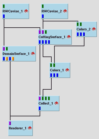
We redesign the pipeline for covise/net/tutorial_pressure_1.net.
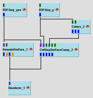
We get the same output with the following simplified pipeline.
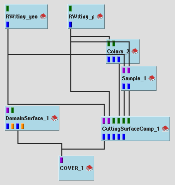
And to conclude this documentation to CuttingSurfaceComp we show in the following example how it supersedes old module CuttingSurface3DTex.
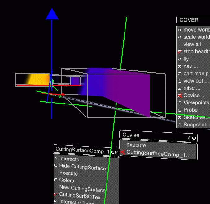
A snapshot of the COVER with the required menu adjustments is shown below.
| Authors: Martin Aumüller, Ruth Lang, Daniela Rainer, Jürgen Schulze-Döbold, Andreas Werner, Peter Wolf, Uwe Wössner |
| Copyright © 1993-2022 HLRS, 2004-2014 RRZK, 2005-2014 Visenso |
COVISE Version 2021.12
|