| Overview | All Modules | Tutorial | User's Guide | Programming Guide |
Module category: IO
ReadANSYS reads .rst, .rfl, and .rth files, which are the results files for mechanical, FLOTRAN or thermal analysis. In all cases READ_ANSYS finds dynamically the degrees of freedom active in the model, from which the user may choose any option for visualisation. As for derived data, the module reads stresses and several kinds of strains for mechanical files, and the heat flux for thermal analysis.
ReadANSYS is available for COVISE version 5.2 and higher. It has been tested on SGI systems (IRIX 6.5).
| Name | Type | Description |
| RST_file | File Browser | Name of .rst .rfl or .rth file. |
| timeSteps | Vector | First set, last set and a number used for skipping sets. |
| ScaleGridDisplacements | Scalar | You may modify the default valule (1.0) in order to amplify or suppress the deformation of the grid. |
| Solution | Choice | You should choose among 3 options: showing only a frozen geometry not influenced by parameter timeSteps, or nodal data (degrees of freedom) or element data (derived results). The two latter options are influenced by the value of timeSteps. |
| DOF_Solution | Choice | The module sets up a list with the degrees of freedom available in the file. The module may also include options for generating vector magnitudes out of these degrees of freedom. This happens if the 3 components are found in the file. The isolated components are output in the nodal coordinate system used in the analysis. However, when you choose oone vector option, the resulting vector field will be rotated into the global coordinate system. |
| Derived_Solution | Choice | You may choose among stresses, elastic strains, plastic strains, creep strains, thermal strains, thermal fluxes and volume or energy-related data per cell. |
| SolidShellComponents | Choice | The value of this selection influences the magnitude associated with solid elements and shells. You may choose among XX, YY, ZZ, XY, YZ, ZX, T1, T2, T3, TI and TIGE. The first 6 valid choices determine the component of the relevant symmetric tensor (chosen through Derived_Solution) selected for output. T1, T2, T3 stand for principal values of the tensor and are only available for stresses. TI stands for the intensity as defined in the ANSYS manuals and is only available for stresses. TIGE stands for the equivalent value and is available in principle for stresses and strains. If you want to compare the results produced by choosing one of the possible components with the images of the ANSYS postprocessor, you will have to introduce the APDL command rsys, solu, which makes ANSYS show results in the same coordinate system as used for their being saved in the results file. |
| BeamComponents | Choice | You may choose among the axial, Yp, Ym, Zp, Zm options. Stresses or strains for beam elements are referred to an element coordinate system whose X component is aligned with the beam. Yp, Ym (Zp, Zm) refer to the state at the positive and negative side respectively along the local Y (Z) direction. |
| AxiShellComponents | Choice | For axisymmteric shells the available components are not the ones listed by SolidShellComponents, but Meridional, ThroughThickness, Hoop and Meridional-hoop. |
| TopBottom | Choice | For shells you may select if the data is shown for the top or the bottom side. You may also choose to average both results. For multilayered shells you might see false results, if keyopt(8) is 1. |
| ThermalFlux | Choice | You may choose among the 3 independent components of the the heat flux, or choose the vector itself. |
| VolEnergy | Choice | You may select volume, strain enery or kinetic energy per cell. |
| OutputNodeDecode | Boolean | for special applications only - not recommended |
| AlwaysVertexBased | Boolean | if turned on cell based data is automatically converted to vertex based data |
| MagFluxDens | Choice | For electromagnetical applications only! Choose the component of the magnetical flux-density to be read. |
|
|
| Name | Type | Description |
| optionalFileName | Text | String with the path of the results file. This object may have a READ_ANSYS attribute. In this case the value (string) of this attribute may be used in order to override the values of the module parameters. As you are not likely to use this feature, we ask you to contact VISENSO for more information if you should ever wish to use it. |
| Name | Type | Description |
| outputGrid | UnstructuredGrid | In general you will get a dynamic set. It may be that there are elements for which the wished output data is not available or simply not meaningful. Then one time step may be itself a set with two elements: one with the grid with data and one for the grid without data. |
| outputData |
Float Vec3 IntArr | Output data. |
| outputMaterials | IntArr | A set of sets with the same structure as the grid with material labels for the elements. You may find this object useful to visualise parts of the grid using SelectUsg . |
|
|
| Element name | Geometric representation | Derived data support |
| LINK1 | TYPE_BAR | LINK |
| PLANE2 | TYPE_TRIANGLE | PLANE |
| BEAM3 | TYPE_BAR | BEAM3 |
| BEAM4 | TYPE_BAR | BEAM4 |
| SOLID5 | TYPE_HEXAEDER | SOLID |
| LINK8 | TYPE_BAR | LINK |
| LINK10 | TYPE_BAR | LINK |
| LINK11 | TYPE_BAR | -- |
| PLANE13 | TYPE_QUAD | PLANE |
| COMBIN14 | TYPE_BAR | -- |
| PIPE16 | TYPE_BAR | -- |
| MASS21 | TYPE_POINT | -- |
| BEAM23 | TYPE_BAR | LINK |
| BEAM24 | TYPE_BAR | LINK |
| PLANE25 | TYPE_QUAD | PLANE |
| SHELL28 | TYPE_QUAD | SHELL |
| LINK31 | TYPE_BAR | -- |
| LINK32 | TYPE_BAR | -- |
| LINK33 | TYPE_BAR | -- |
| LINK34 | TYPE_BAR | -- |
| PLANE35 | TYPE_TRIANGLE | THERMAL_PLANE |
| COMBIN37 | TYPE_BAR | -- |
| COMBIN39 | TYPE_BAR | -- |
| COMBIN40 | TYPE_BAR | -- |
| SHELL41 | TYPE_QUAD | SHELL |
| PLANE42 | TYPE_QUAD | PLANE |
| PLANE43 | TYPE_QUAD | SHELL |
| BEAM44 | TYPE_BAR | BEAM4 |
| SOLID45 | TYPE_HEXAEDER | SOLID |
| SOLID46 | TYPE_HEXAEDER | SOLID |
| SHELL51 | TYPE_BAR | AXI_SHELL |
| BEAM54 | TYPE_BAR | BEAM3 |
| PLANE55 | TYPE_QUAD | THERMAL_PLANE |
| HYPER56 | TYPE_QUAD | SOLID |
| SHELL57 | TYPE_QUAD | THERMAL_PLANE |
| HYPER58 | TYPE_HEXAEDER | SOLID |
| SHELL61 | TYPE_BAR | -- |
| SHELL63 | TYPE_QUAD | SHELL |
| SOLID64 | TYPE_HEXAEDER | SOLID |
| SOLID65 | TYPE_HEXAEDER | SOLID |
| SOLID70 | TYPE_HEXAEDER | THERMAL_SOLID |
| MASS71 | TYPE_POINT | -- |
| HYPER74 | TYPE_QUAD | PLANE |
| PLANE75 | TYPE_QUAD | -- |
| PLANE77 | TYPE_QUAD | THERMAL_PLANE |
| PLANE78 | TYPE_TRIANGLE | -- |
| PLANE82 | TYPE_QUAD | PLANE |
| PLANE83 | TYPE_QUAD | PLANE |
| HYPER84 | TYPE_QUAD | PLANE |
| HYPER86 | TYPE_HEXAEDER | SOLID |
| SOLID87 | TYPE_TETRAHEDER | THERMAL_SOLID |
| VISCO88 | TYPE_QUAD | PLANE |
| VISCO89 | TYPE_HEXAEDER | SOLID |
| SOLID90 | TYPE_HEXAEDER | THERMAL_SOLID |
| SHELL91 | TYPE_QUAD | SHELL |
| SOLID92 | TYPE_TETRAHEDER | SOLID |
| SHELL93 | TYPE_QUAD | SHELL |
| SOLID95 | TYPE_HEXAEDER | SOLID |
| SHELL99 | TYPE_QUAD | SHELL |
| VISCO106 | TYPE_QUAD | PLANE |
| VISCO107 | TYPE_HEXAEDER | SOLID |
| VISCO108 | TYPE_QUAD | PLANE |
| FLUID141 | TYPE_QUAD | -- |
| FLUID142 | TYPE_HEXAEDER | -- |
| SHELL143 | TYPE_QUAD | SHELL |
| PLANE145 | TYPE_QUAD | PLANE |
| PLANE146 | TYPE_TRIANGLE | PLANE |
| SOLID147 | TYPE_HEXAEDER | SOLID |
| SOLID148 | TYPE_TETRAHEDER | SOLID |
| SHELL150 | TYPE_QUAD | SHELL |
| SOLID158 | TYPE_TETRAHEDER | SOLID |
| TARGE169 | TYPE_TARGET_2D | -- |
| TARGE170 | TYPE_TARGET | -- |
| SOLID181 | TYPE_QUAD | SHELL |
| PLANE182 | TYPE_QUAD | PLANE |
| PLANE183 | TYPE_QUAD | PLANE |
| SOLID185 | TYPE_HEXAEDER | SOLID |
| SOLID186 | TYPE_HEXAEDER | SOLID |
| SOLID187 | TYPE_TETRAHEDER | SOLID |
| SOLID191 | TYPE_HEXAEDER | SOLID |
Elements not appearing in this list will be invisible for COVISE.
The code of the third column establishes which derived magnitudes you may read for the element at issue. When no code is present, only DOF data is available for output. Nevertheless you will see the geometry of those elements even when you request derived data.
Output for elements with code SOLID, PLANE or SHELL is controlled by parameter SolidShellComponents. In the case of SHELL you may control with parameter TopBottom for which face of the shell you want to retrieve results, or make an average. If you use are using multilayered elements, you ought to set KEYOPT(8) for the pertinent element type in ANSYS to the value 0. If you work with KEYOPT(8) set to 1, you will not be able to access inner layers, and according to our tests, you may access only TOP and BOTTOM as if KEYOPT(8) were 0, nevertheless, according to the documented structure of the .rst file, false values could be produced in this case.
Derived output for elements with code BEAM3 and BEAM4 is controlled with parameter BeamComponents, whose last two options apply only to 3D beams (BEAM4).
Derived output for elements with code AXI_SHELL is controlled by parameter AxiShellComponents.
Derived output for elements with code THERMAL_PLANE or THERMAL_SOLID are both controlled by parameter ThermalFlux.
The geometric representation for target elements is based on their nodes. If their true geometry is given by a shape such that it is not fully represented by the nodes, the representation may be drastically simplified. So, as far as TARGET170 is concerned, spherical targets are represented by a single node at the centre, cones and cylinders are represented by two-noded bars. As for TARGET169, parabolic and arc target elements, which have 3 nodes, are represented by a bar with the two end nodes; and targets with circle shape are represented by a single node at the centre.
We present below two examples.
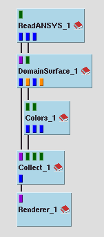
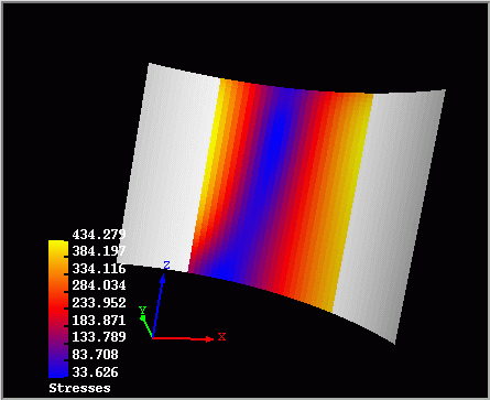
This example shows a model modified from example vm6.dat of the verification collection of ANSYS. Derived data is available only for some elements. The output for the equivalent stresses on the top side of the shell elements is shown below.
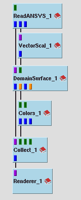
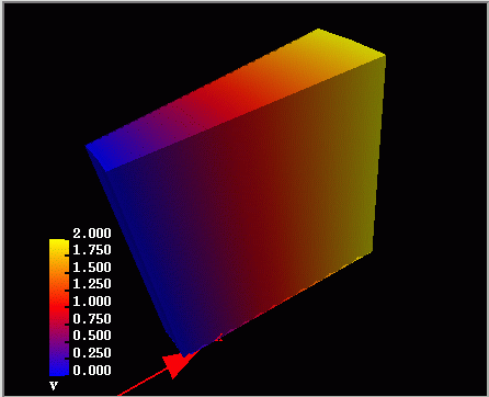
The other exemple is based on the second net file.
The magnitude of the velocity for the final available set of the simulation is produced below.
| Authors: Martin Aumüller, Ruth Lang, Daniela Rainer, Jürgen Schulze-Döbold, Andreas Werner, Peter Wolf, Uwe Wössner |
| Copyright © 1993-2022 HLRS, 2004-2014 RRZK, 2005-2014 Visenso |
COVISE Version 2021.12
|